
Heat-dissipating device for a projection apparatus

a technology of heat dissipation device and projection apparatus, which is applied in the direction of lighting and heating apparatus, instruments, transportation and packaging, etc., can solve the problems of affecting the small broken pieces scattered over the projection apparatus, and the explosion or burnout of the lamp unit b>4/b>, so as to reduce the intense heat and enhance the cooling effect of the projection apparatus.

Inactive Publication Date: 2009-10-27
YOUNG OPTICS
View PDF31 Cites 12 Cited by
  • Summary
  • Abstract
  • Description
  • Claims
  • Application Information

AI Technical Summary

Benefits of technology

The present invention provides a heat-dissipating device for a projection apparatus. The device includes a fan unit mounted to reduce heat at the exterior and interior of the reflector, improving cooling in the projection apparatus. The device also includes a protective net to prevent scattered pieces from causing damage in case of a lamp burnout. The device helps to lower temperature by airflow and ensures proper cooling for the projection apparatus.

Problems solved by technology

Moreover, the lamp unit 4 may explode or burnout due to the intensive heat.
It is relatively difficult to clean the tiny broken pieces scattered over the projection apparatus 2.

Method used


Image

  • Heat-dissipating device for a projection apparatus
  • Heat-dissipating device for a projection apparatus
  • Heat-dissipating device for a projection apparatus

Examples


Embodiment Construction

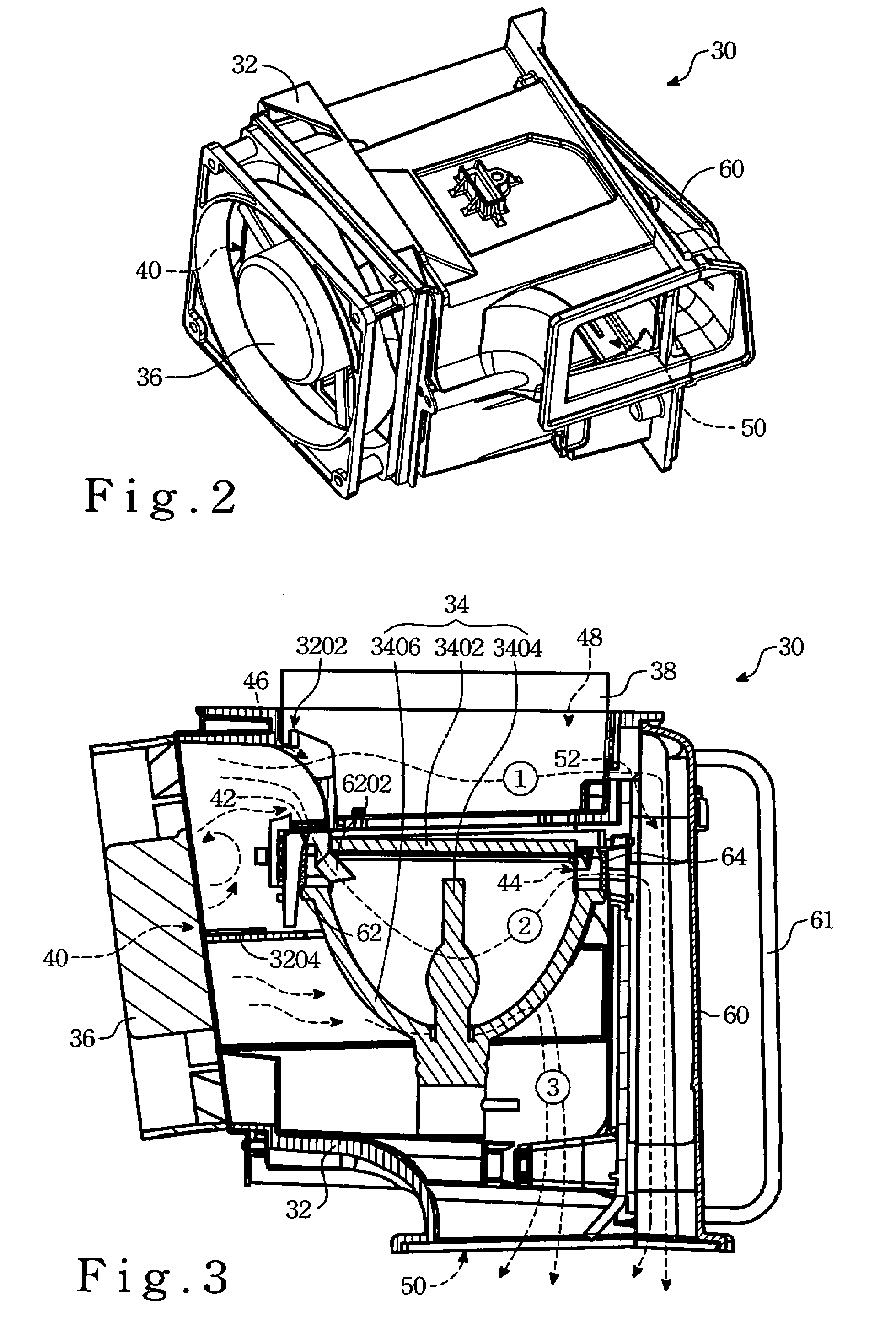
[0018]FIG. 2 is a perspective view of the heat-dissipating device 30 of the present invention and is used in a projection apparatus (not shown) in order to lower the intensive heat (temperature) caused by a lamp unit due to operation of the apparatus.

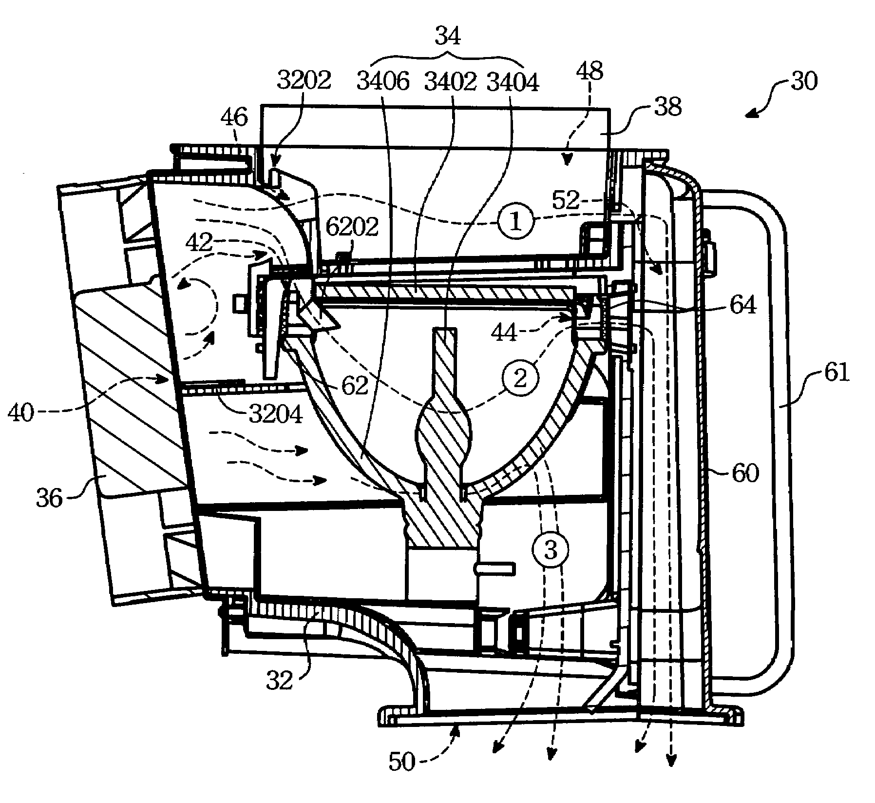
[0019]FIG. 3 is a top sectional view of the heat-dissipating device of the present invention, and includes a receptacle body 32, a lamp unit 34, a fan unit 36, a nozzle 3202 and an air guide partition 3204.

[0020]The receptacle body 32 has a lateral left wall formed with a left air vent 40. The lamp unit 34 is disposed in the receptacle body 32, and includes a burner 3404, a generally concave reflector 3406 surrounding the burner 3404, and a glass plate 3402 disposed in front of the reflector 3406. The reflector 3406 cooperates with the glass plate 3402 to define an air inlet 42 adjacent to the left air vent 40 and an air outlet 44 spaced from the left air vent 40.

[0021]The fan unit 36 (preferable an axial fan) is mounted on the receptac...


PUM


Abstract

A heat-dissipating device includes a receptacle body having a lateral wall formed with an air vent; a lamp unit including a burner, a reflector covered the burner, a glass plate disposed in front of the reflector, the reflector cooperating with the glass plate to define an air inlet adjacent to the air vent and an air outlet spaced from the air vent; a fan unit mounted on the receptacle body for covering the air vent and for generating airflow to flow into the receptacle body; and a nozzle disposed within the receptacle body between the air vent and the lamp unit for guiding the airflow into the lamp unit.

Description

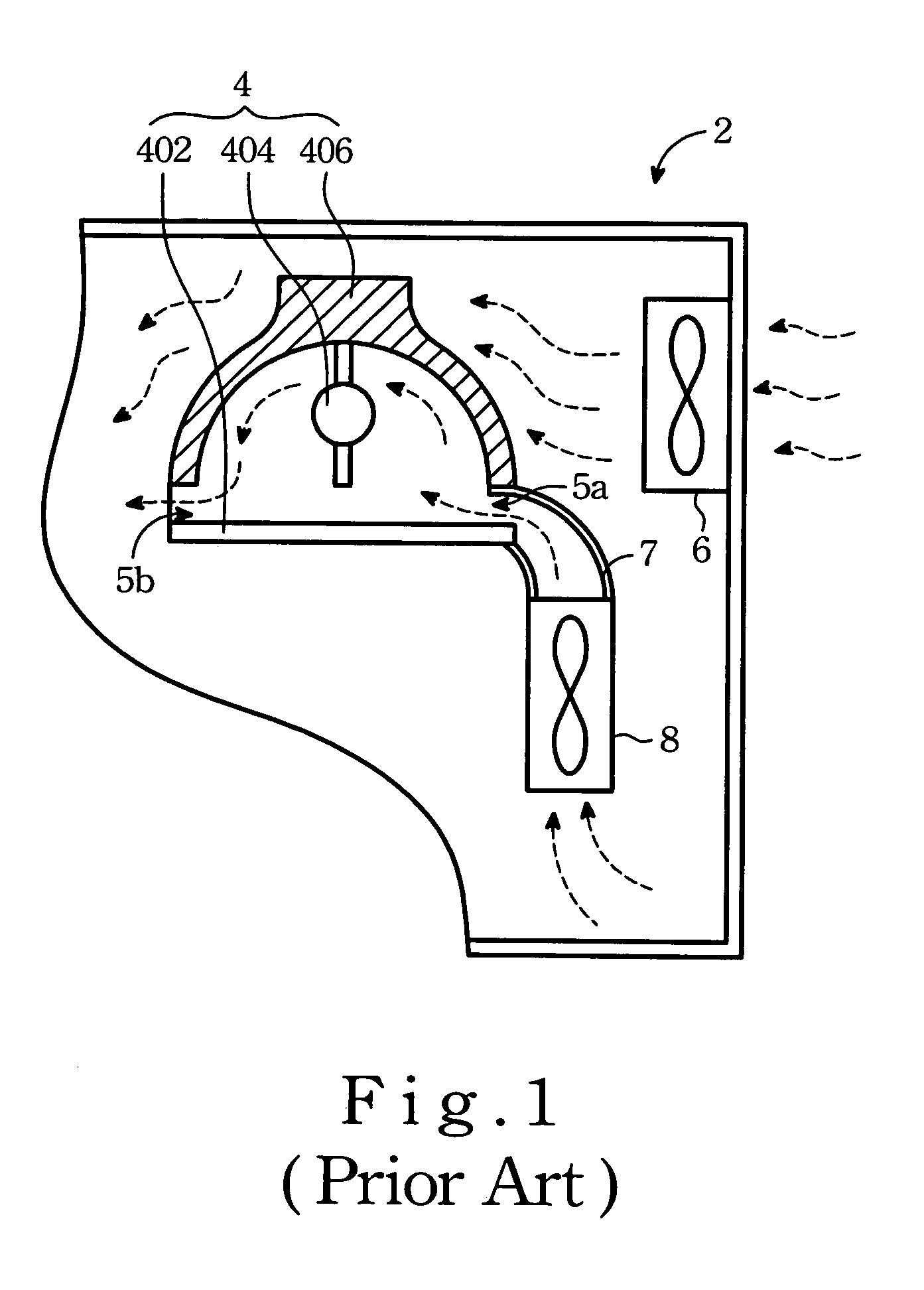
FIELD OF THE INVENTION[0001]The invention relates to a heat-dissipating device, and more particularly to a heat-dissipating device for a projection apparatus in order to dissipate the intensive heat generated due to operation of the projection apparatus.BACKGROUND OF THE INVENTION[0002]FIG. 1 is a top sectional view of a conventional projection apparatus 2, and includes a lamp unit 4 for producing light rays required for projecting an image. The lamp unit 4 includes a burner 404, a reflector 406 surrounding the burner 404, and a glass cover 402 disposed in front of the reflector 406. The reflector 406 and the glass cover 402 cooperatively define an air inlet 5a at one side of the reflector 406 and an air outlet 5b at the other side of the reflector 406.[0003]In order to reduce the intensive heat generated during use, an axial fan unit 6 is usually provided at one side of the reflector 406, thereby lowering the temperature at an outer side of the reflector 406. A blower 8 is further ...

Claims


Application Information

Patent Timeline
Patent Type & Authority Patents(United States)
IPC IPC(8): G03B21/18B60Q1/06F21V29/00F21V7/20F21V29/505
CPCG03B21/16
Inventor YUN, CHI-CHUILIN, HUNG-YINGHUANG, JIA-BIN
Owner YOUNG OPTICS
Learn More