Heating and cooling module for battery

a battery and module technology, applied in the direction of cell components, electrical equipment, cell temperature control, etc., can solve the problem of disabled heating elements, achieve the effect of reducing the temperature of the battery module, increasing service life and working efficiency, and improving service li

Inactive Publication Date: 2013-03-28
ASIA VITAL COMPONENTS SHENZHEN CO LTD
View PDF8 Cites 8 Cited by
  • Summary
  • Abstract
  • Description
  • Claims
  • Application Information

AI Technical Summary

Benefits of technology

[0005]Another object of the present invention is to provide a heating and cooling module for lowering a high temperature of a battery during the operation thereof, so as to protect the battery against overheating.
[0007]The heat exchanger unit is arranged in an enclosure of a battery module to face toward a plurality of battery cells of the battery module. The heating element is located to one lateral side of the heat exchanger unit for generating heat, and the air-guiding element is located at one side of the heating element opposite to the heat exchanger unit for sucking in hot air from the heating element to raise the temperature in a working environment of the battery module. On the other hand, when the battery module is overheated during working, the heating element is disabled and the air-guiding element sucks in cold air from the heat exchanger unit to lower the temperature of the battery module. In this manner, the battery module can have largely increased service life and working efficiency.
[0008]In brief, the heating and cooling module for battery according to the present invention has the following advantages: (1) maintaining a battery at a desired working temperature; (2) giving the battery increased service life; and (3) allowing the battery to have upgraded working efficiency.

Problems solved by technology

On the other hand, when the battery module is overheated during working, the heating element is disabled and the air-guiding element sucks in cold air from the heat exchanger unit to lower the temperature of the battery module.

Method used


Image

  • Heating and cooling module for battery
  • Heating and cooling module for battery
  • Heating and cooling module for battery

Examples


Embodiment Construction

[0015]The present invention will now be described with some preferred embodiments thereof and with reference to the accompanying drawings. For the purpose of easy to understand, elements that are the same in the preferred embodiments are denoted by the same reference numerals.

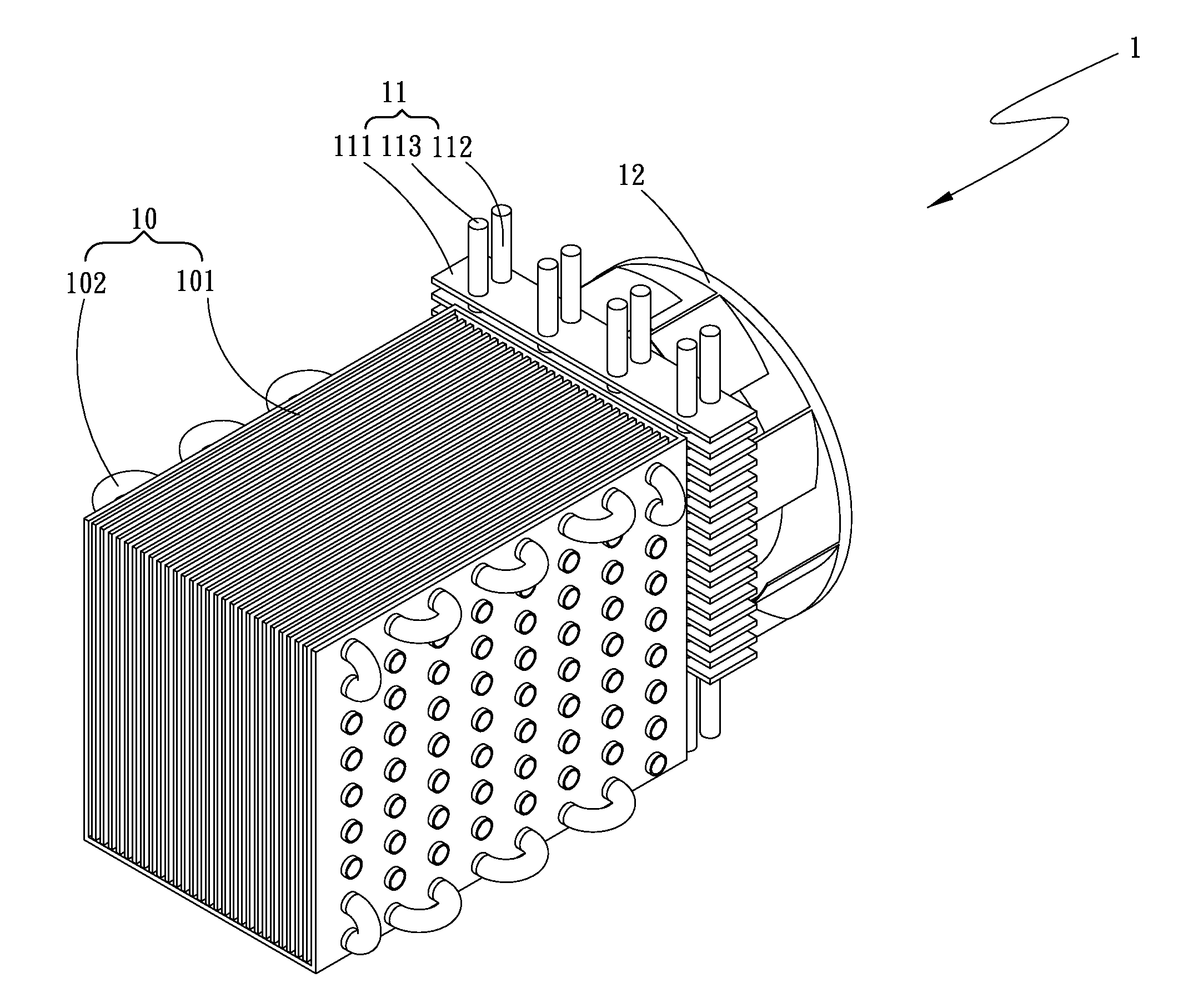
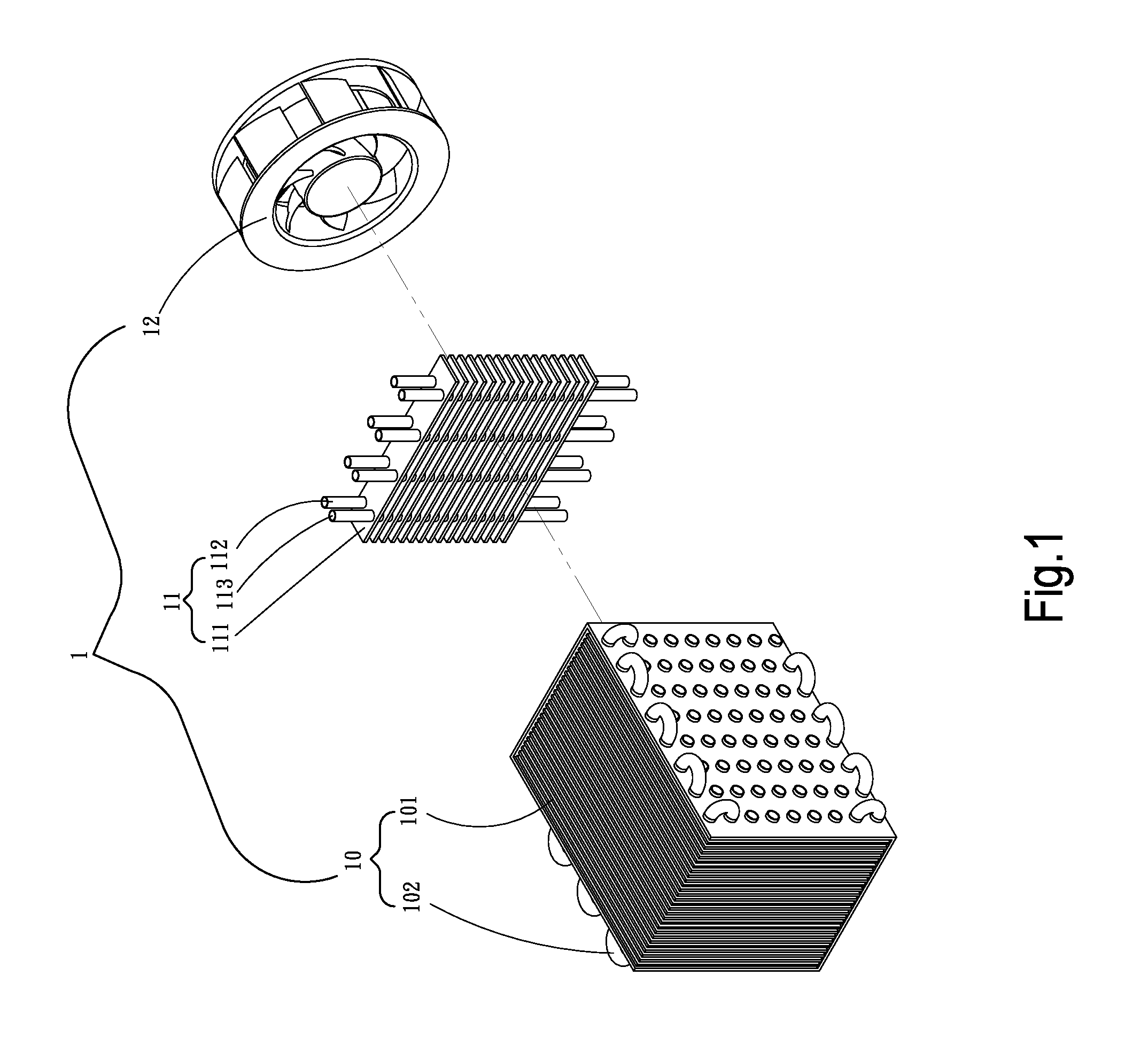
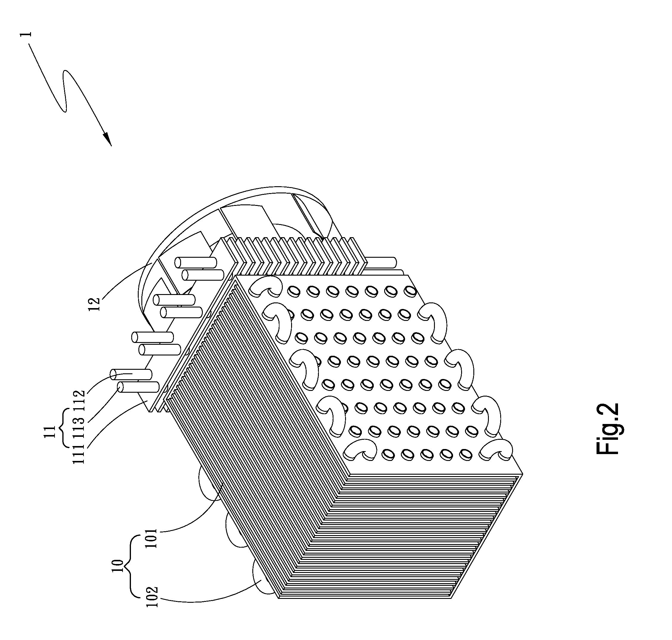
[0016]Please refer to FIGS. 1 and 2 that are exploded and assembled perspective views, respectively, of a heating and cooling module for battery according to a first preferred embodiment of the present invention. For the purpose of conciseness, the present invention is also briefly referred to as a “heating and cooling module” herein and is generally denoted by reference numeral 1. As shown, the heating and cooling module 1 includes a heat exchanger unit 10, a heating element 11, and an air-guiding element 12.

[0017]The heat exchanger unit 10 can be any one of a vapor chamber, a heat-conducting metal device, such as a copper heat sink or an aluminum heat sink, and a water cooler. In the illustrated first preferr...


PUM

PropertyMeasurementUnit
temperatureaaaaaaaaaa
electric poweraaaaaaaaaa

Abstract

A heating and cooling module for battery is used with a battery module and includes a heat exchanger unit, a heating element, and an air-guiding element. The heat exchanger unit is arranged in an enclosure of the battery module to face toward a plurality of battery cells of the battery module. The heating element is located to one lateral side of the heat exchanger unit, and the air-guiding element is located at one side of the heating element opposite to the heat exchanger unit. With the heating and cooling module, hot air and cold air can be supplied to heat or cool down the battery module according to actual need, so that the battery module can maintain at its normal working temperature to largely increase its service life and working efficiency.

Description

FIELD OF THE INVENTION[0001]The present invention relates to a heating and cooling module for battery, and more particularly to a heating and cooling module for maintaining a battery module at its normal working temperature and protecting the battery module against overheating.BACKGROUND OF THE INVENTION[0002]In the occasion where household AC power or general DC power is not available, a battery is usually used to supply electric power. For instance, various kinds of vehicles, lamps, power tools, electronic devices, communication devices and heat exchangers all can use one or more batteries to obtain required power supply. However, a battery could not be activated to supply power in a working environment having a low temperature from about −20° C. to about −30° C. Therefore, in extremely cold areas or countries and in working places that require very low temperature, special measures have been taken to heat batteries for them to reach and maintain at a desired working temperature t...

Claims


Application Information

Patent Timeline
Patent Type & Authority Applications(United States)
IPC IPC(8): H01M10/50H01M10/613H01M10/615H01M10/65H01M50/209
CPCH01M2/1016H01M10/5004H01M10/5067H01M10/5057H01M10/5006H01M10/613H01M10/615H01M10/6551H01M10/6552H01M10/6556H01M10/6563Y02E60/10H01M50/209
Inventor CHIU, TZU-CHIN
Owner ASIA VITAL COMPONENTS SHENZHEN CO LTD
Why Eureka
Try Eureka