Electric connector for circuit board

a technology of electrical connectors and circuit boards, applied in the direction of coupling devices, two-part coupling devices, electrical apparatus, etc., can solve the problem of limit design of circuit boards, and achieve the effect of reducing the height of the connector

Inactive Publication Date: 2009-10-27
HIROSE ELECTRIC GROUP
View PDF19 Cites 10 Cited by
  • Summary
  • Abstract
  • Description
  • Claims
  • Application Information

AI Technical Summary

Benefits of technology

[0008]A width direction size of the connector of this type is not an important issue. However, a lengthwise direction size of such connector; that is, a height of the connector on the circuit board is demanded to be minimized. This is to reduce a size of an electrical device that is configured through piling a plurality of the circuit boards of the similar type.
[0009]However, in the connector described above and shown in FIG. 7, a fitting contact portion of the mating connector is positioned above the U character shape elastic arm portion of the terminal of the connector arranged on the circuit board. Accordingly, the lower portion of the elastic arm portion and the lower portion of the fitting contact portion are overlapped in a top-to-bottom direction; thereby a height direction of the connector is enlarged.
[0015]As previously described, according to the present invention, the terminal inside the terminal receptacle groove and the mating terminal do not overlap each other in the height direction. Accordingly, the height of the connector can be reduced, which contributes to provide a low-profile connector.

Problems solved by technology

This causes an inconvenience that limits designing of the circuit board.

Method used


Image

  • Electric connector for circuit board
  • Electric connector for circuit board
  • Electric connector for circuit board

Examples


Embodiment Construction

[0023]Hereunder, an electrical connector for a circuit board according to an embodiment of the present invention will be explained with reference to the accompanying drawings, i.e., FIGS. 1 to 6.

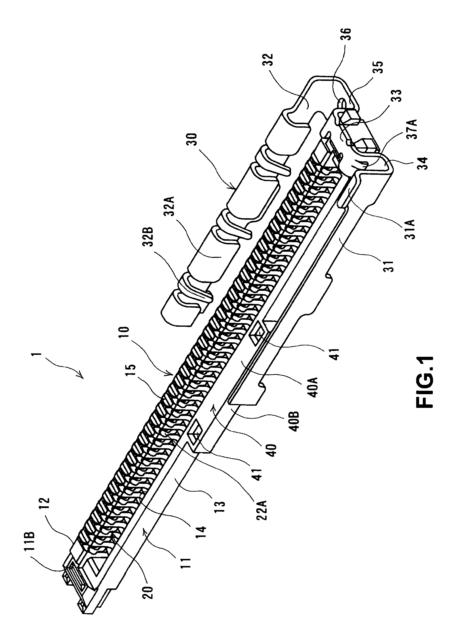
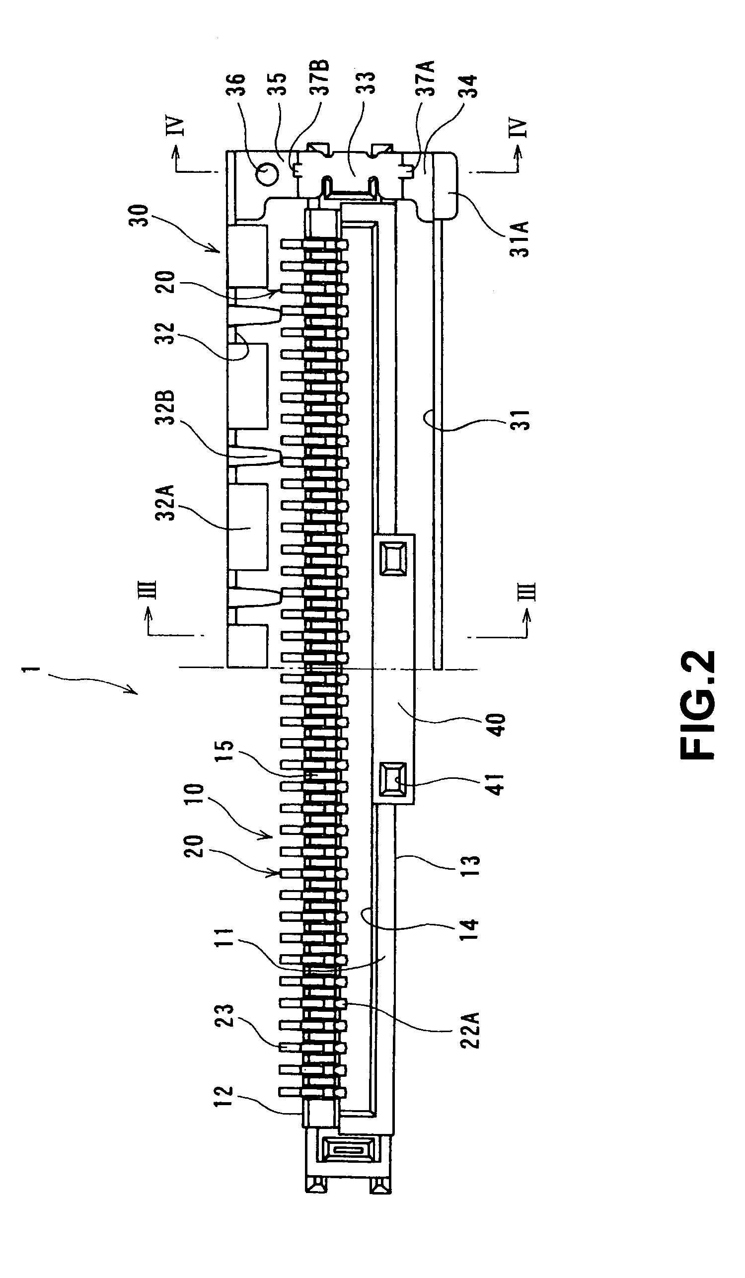
[0024]FIG. 1 is a perspective view showing a whole configuration of the connector according to the embodiment, and FIG. 2 is a plan view thereof. In both figures, a left half of a ground plate attached to the connector is omitted in the longitudinal direction.

[0025]A connector 1 is formed to attach to a circuit board (not shown), and extends in left and right directions as shown in the figures. In the connector 1, a ground plate 30 is selectively attached to a connector main body 10.

[0026]In the connector main body 10, a plurality of terminals 20 is arranged with a specific interval on an outer side surface 12 among the outer side surfaces 12 and 13 situated in a longitudinal direction of a housing 11 formed of an insulation material and elongated in the left and right directions.

[0027]The h...


PUM


Abstract

A fitting portion 21 of a terminal 20 is formed in an inverted U character shape along an outer surface and an upper surface of a housing sidewall portion and an interior of a receptacle groove 16; an elastic arm portion 22 bends and extends from the fitting portion to form a U character shape; the bent portion reaches a bottom portion 14B of the receptacle groove in a connector fitting direction; the elastic arm portion extends upward inside the receptacle groove from the bent portion and has elasticity in an area up to a free edge; the elastic arm portion has a contact portion 22A slightly protruding from the inner side surface 14C of the fitting recess portion; the fitting recess portion 14 forms a space between the inner side surface and an opposite inner side surface for receiving a fitting contact portion of the mating connector; the fitting contact portion of the mating connector presses the contact portion 22A of the terminal toward inside the receptacle groove 16; and a distal portion of the fitting contact portion in a connector fitting direction enters toward a bottom portion of the fitting recess portion up to a position substantially the same as that of the bent portion of the terminal.

Description

FIELD OF THE INVENTION[0001]The present invention relates to an electrical connector to be attached to a circuit board in use.DESCRIPTION OF THE RELATED ART[0002]A connector disclosed in FIG. 7 has been known as a connector of this type.[0003]In a connector 50 shown in FIG. 7, a receptacle groove 52 with an upward opening and a bottom wall 52A is provided in a housing 51 and retains a part of a terminal 53. The receptacle groove 52 opens upward. Further, a top portion of a sidewall portion 54 of the housing 51 is cut off, and there is an opening on this side. This receptacle groove 52 is sized to have a width of the terminal 53 that is bent and has a band shape. That is, the width in a direction perpendicular to a sheet surface is determined.[0004]The terminal 53 having a band shape has a substantially S character shape; that is, continuously a U character shape portion and an inverted U character shape portion. An elastic arm portion 53A is provided in the U character shape portion...

Claims


Application Information

Patent Timeline
Patent Type & Authority Patents(United States)
IPC IPC(8): H01R9/05H01R12/71
CPCH01R12/62H01R12/598H01R2103/00
Inventor KENJO, MITSUNORI
Owner HIROSE ELECTRIC GROUP
Why Eureka
Try Eureka