Stacked type piezoelectric element and vibration wave motor

a piezoelectric element and vibration wave technology, applied in piezoelectric/electrostrictive/magnetostrictive devices, piezoelectric/electrostriction/magnetostriction machines, electrical equipment, etc., can solve the imbalance between the phase a and the phase b, the traveling wave is generated uneven, and the unevenness of the traveling wave is large than expected

Inactive Publication Date: 2009-10-27
CANON KK
View PDF15 Cites 5 Cited by
  • Summary
  • Abstract
  • Description
  • Claims
  • Application Information

AI Technical Summary

Problems solved by technology

However, in a case where the stacked type piezoelectric element with the conventional structure is used for a more compact vibration wave motor, larger-than-expected unevenness of traveling wave is caused.
In other words, an imbalance between the phase A and the phase B is caused due to the capacitance of the sensor phase which is provided in the same phase as the phase A serving as a sensing means for monitoring a vibration state of the vibration device of the stacked type piezoelectric element used for the compact vibration device.
Such the imbalance is supposed to be a major cause of the generation of unevenness of the traveling wave.

Method used


Image

  • Stacked type piezoelectric element and vibration wave motor
  • Stacked type piezoelectric element and vibration wave motor
  • Stacked type piezoelectric element and vibration wave motor

Examples


first embodiment

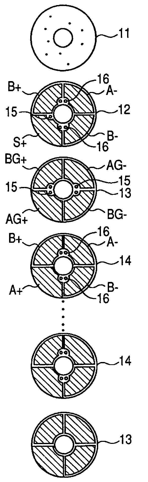
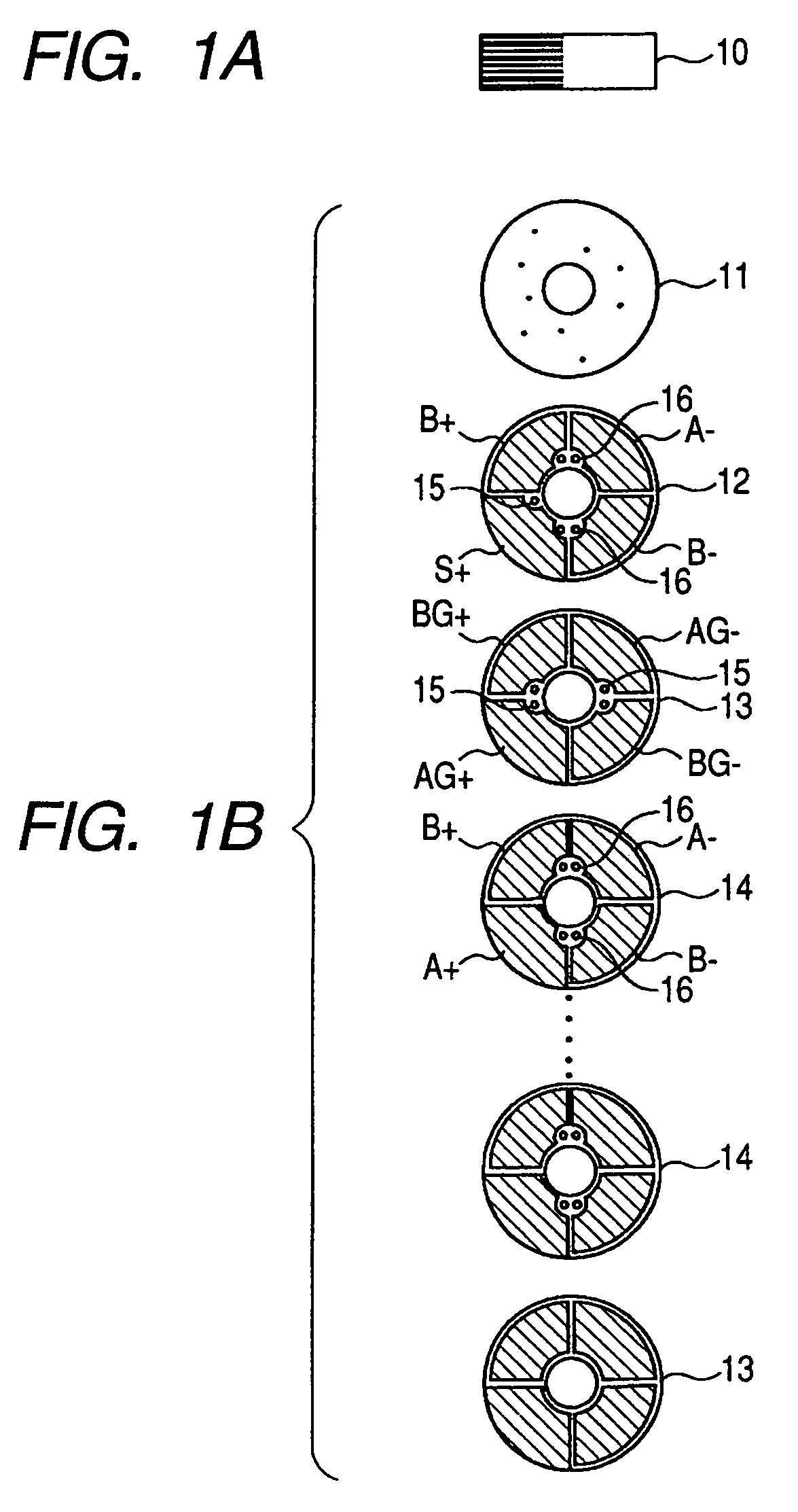
[0044]FIG. 1A is an elevation of a stacked type piezoelectric element according to a first embodiment of the present invention, and FIG. 1B is a diagram of the stacked type piezoelectric element shown in FIG. 1A which is broken down into piezoelectric layers.

[0045]As shown in FIG. 1A, a stacked type piezoelectric element 10 has a cylindrical laminated structure in which a plurality of piezoelectric layers are stacked. As shown in FIG. 1B, in the stacked type piezoelectric element 10, a surface electrode layer 11 is arranged as a first layer, and a piezoelectric layer (sensor layer) 12 is arranged as a second layer. From a third layer to an N-th layer of the stacked type piezoelectric element 10, piezoelectric layers 13 and piezoelectric layers 14 are alternately arranged. The piezoelectric layers 12 to 14 are formed in the same cylindrical shape and have an opening at respective center portions thereof.

[0046]The surface electrode layer 11 is provided with nine surface electrodes (bl...

second embodiment

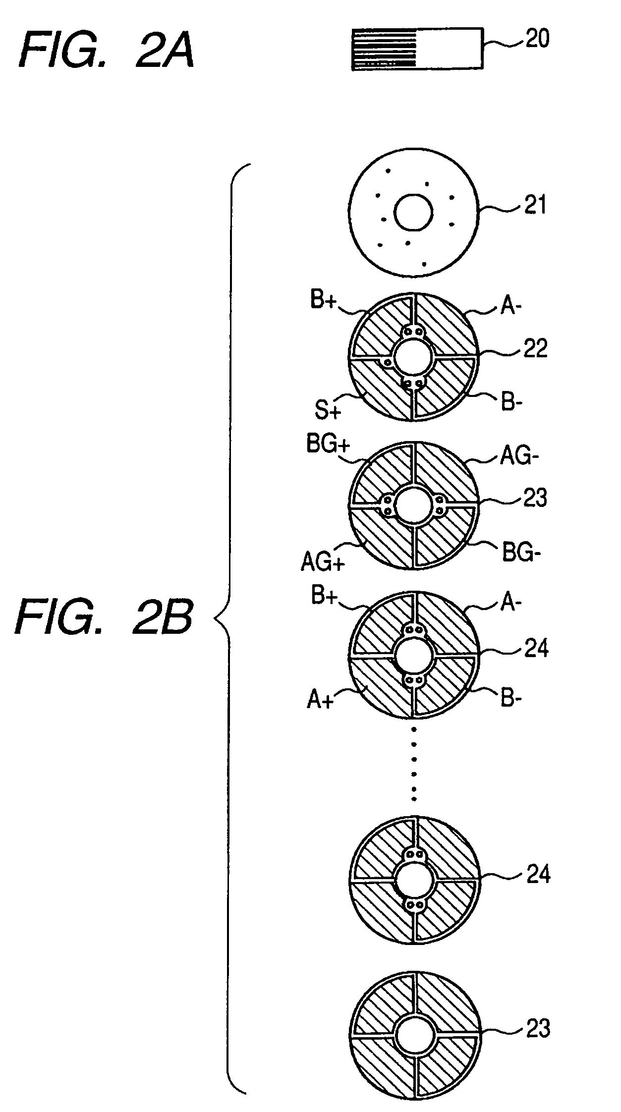
[0052]Next, a second embodiment of the present invention will be described with reference to FIGS. 2A and 2B. FIG. 2A is an elevation of a stacked type piezoelectric element according to the second embodiment of the present invention, and FIG. 2B is a diagram of the stacked type piezoelectric element shown in FIG. 2A which is broken down into piezoelectric layer.

[0053]As shown in FIG. 2A, a stacked type piezoelectric element 20 of this embodiment has a cylindrical laminated structure in which a plurality of piezoelectric layers are stacked. As shown in FIG. 2B, a surface electrode layer 21 and piezoelectric layers 22 to 24 that constitute the stacked type piezoelectric element 20 are structured in the same manner as in the first embodiment. However, the stacked type piezoelectric element 20 is structured in such a manner that inner electrodes A+ and AG+, which are arranged in the same phase as an inner electrode S+ serving as a sensor phase, and inner electrodes A− and AG−, which ar...

third embodiment

[0056]Next, a third embodiment of the present invention will be described with reference to FIGS. 3A and 3B. FIG. 3A is an elevation of a stacked type piezoelectric element according to the third embodiment of the present invention, and FIG. 3B is a diagram of the stacked type piezoelectric element shown in FIG. 3A which is broken down into piezoelectric layers.

[0057]As shown in FIG. 3A, a stacked type piezoelectric element 30 according to this embodiment has a laminated structure in a shape of a rectangular parallelepiped in which a plurality of piezoelectric layers are stacked and whose cross-section has a square shape. As shown in FIG. 3B, a surface electrode layer 31 and piezoelectric layers 32 to 34 that constitute the stacked type piezoelectric element 30 are structured in the same manner as in the first embodiment. However, in the stacked type piezoelectric element 30, an inner electrode S+ serving as a sensor phase, and inner electrodes A+ and AG+ which are arranged in the s...


PUM


Abstract

Provided is a stacked type piezoelectric element including a surface electrode layer as a first layer and a piezoelectric layer as a second layer. A third layer to an N-th layer thereof are formed by alternately arranging piezoelectric layers and piezoelectric layers. A surface of the piezoelectric layer is provided with four-way split inner electrodes S+, B+, A−, and B−. A surface of the piezoelectric layer is provided with four-way split inner electrodes AG+, BG+, AG−, and BG−. A surface of the piezoelectric layer is provided with four-way split inner electrodes of A+, B+, A−, and B−. The piezoelectric layers are formed such that only the inner electrode S+ serving as a sensor phase and the inner electrodes A+ and AG+ being arranged in the same phase as the inner electrode S+ are exposed to an outside of the piezoelectric layer.

Description

BACKGROUND OF THE INVENTION[0001]1. Field of the Invention[0002]The present invention relates to a stacked type piezoelectric element and a vibration wave motor.[0003]2. Related Background Art[0004]As an example of electro-mechanical energy conversion elements, there is a stacked type piezoelectric element capable of generating a large deformation distortion and a large force with a low voltage. The stacked type piezoelectric element is disclosed in U.S. Pat. No. 5,770,916, and is used for a vibration wave motor, for example.[0005]The stacked type piezoelectric element of this kind has a laminated structure in which a plurality of piezoelectric layers composed of, for example, piezoelectric ceramics are stacked. On a surface of each piezoelectric layer, inner electrodes composed of an electrode material are formed.[0006]A structure of the stacked type piezoelectric element will be described with reference to FIGS. 7A and 7B. FIG. 7A is a side view of a conventional stacked type piez...

Claims


Application Information

Patent Timeline
Patent Type & Authority Patents(United States)
IPC IPC(8): H01L41/08
CPCH01L41/0471H02N2/106H01L41/0835H10N30/871H10N30/505
Inventor NITTO, KIYOSHIMARUYAMA, YUTAKA
Owner CANON KK
Why Eureka
Try Eureka