Vibrational wave motor, lens barrel and camera

a vibrational wave and motor technology, applied in the field of vibrational wave motors, can solve the problems of raising a new problem for optimizing a velocity control, unsatisfactory drive performance, etc., and achieve the effect of driving quietly and suitable drive performan

Active Publication Date: 2011-11-17
NIKON CORP
View PDF0 Cites 7 Cited by
  • Summary
  • Abstract
  • Description
  • Claims
  • Application Information

AI Technical Summary

Benefits of technology

[0032]According to the present invention, it is possible to provide a vibrational wave motor, ...

Problems solved by technology

However, if the vibration amplitude is too high, the problems arise that the pressurization is not effective for the moving element, abnormal noises occur, or appropriate friction contact cannot be made between the ...

Method used


Image

  • Vibrational wave motor, lens barrel and camera
  • Vibrational wave motor, lens barrel and camera
  • Vibrational wave motor, lens barrel and camera

Examples


first embodiment

[0040]Below, an embodiment of a vibrational wave motor 10 according to the present invention is described in detail referring to the attached drawings.

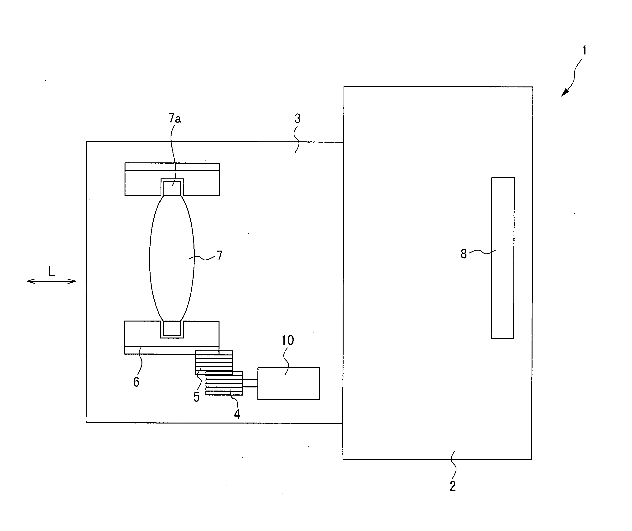
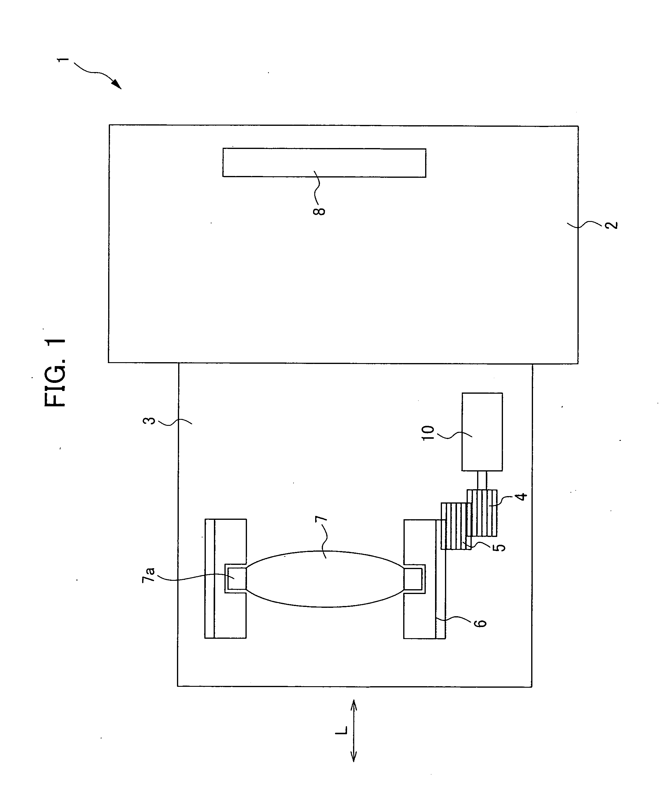
[0041]FIG. 1 is a figure for explaining a camera 1 having a vibrational wave motor 10 of the first embodiment.

[0042]The camera 1 is provided with a camera body 2 having an image pickup device 8, and a lens barrel 3 having a lens 7. The lens barrel 3 is an interchangeable lens that can be attached to and detached from the camera body 2. It should be noted that in the present embodiment, an example in which the lens barrel 3 is an interchangeable lens is shown, but this is not a limitation, and for example, the lens barrel 3 may be a lens barrel integrated with the camera body.

[0043]The lens barrel 3 is provided with a lens 7, a cam tube 6, gears 4, 5, a vibrational wave motor 10 and so on. In the present embodiment, a driving force obtained from the vibrational wave motor 10 is transferred to the cam tube 6 via the gears 4, 5. The lens...

second embodiment

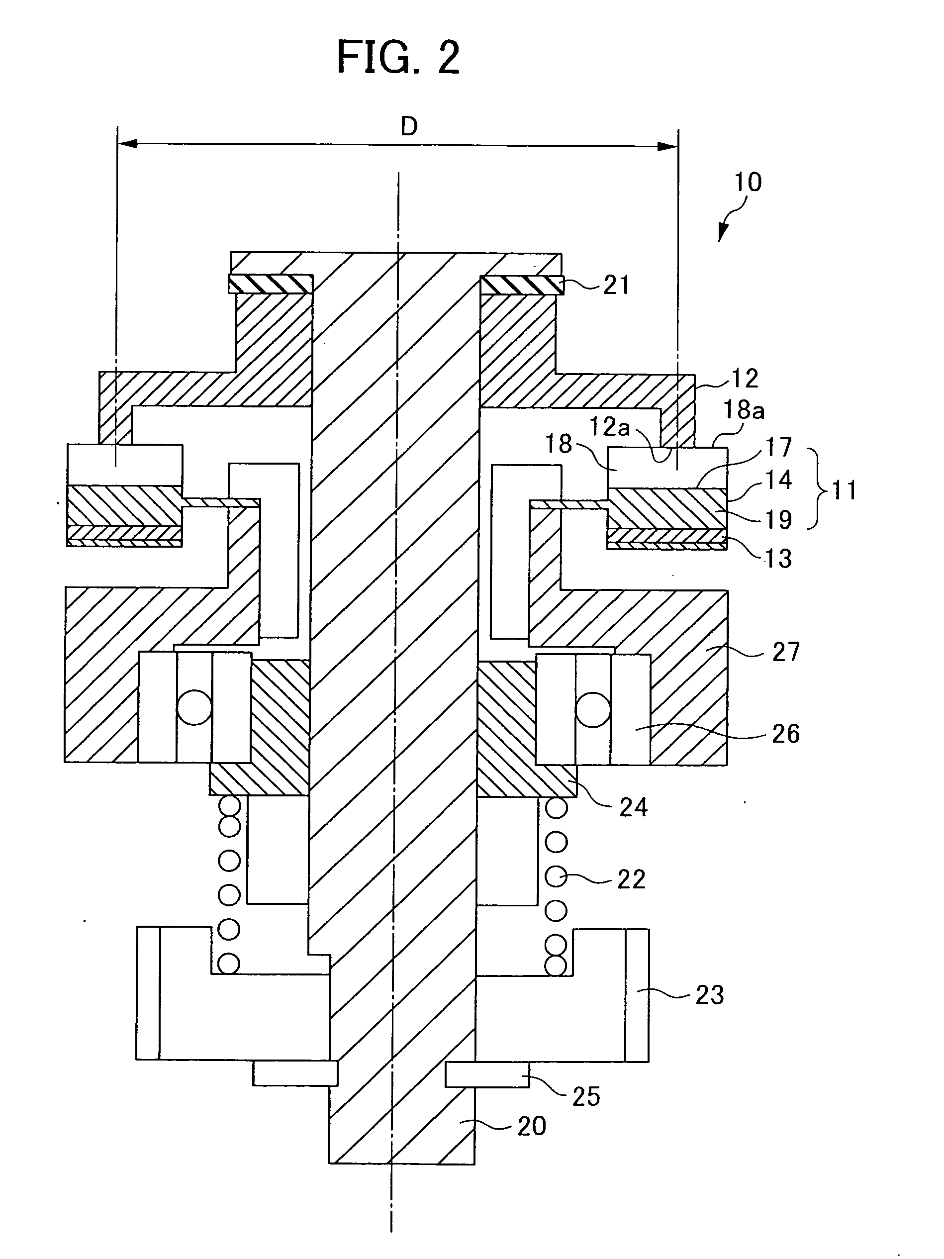
[0114]Next, the second embodiment is described. The vibration amplitude is controlled based on the deformation amount in a pressurized state of the moving element 12.

[0115]In the present embodiment, a vibrational wave motor control device is operated as follows. First, the setting within a factory before shipment is explained.

[0116]At first, D [mm] (the diameter of the sliding surface 12a of the moving element 12), λ [mm] (the wavelength of the moving element 11) and the b-value [mm] (the deformation amount of the moving element 12 in a pressurized state) are calculated and inputted to the control section 52.

[0117]Next, preliminary driving is carried out. For a method therefor, a driving signal is generated from the oscillating section 51, and the signal is divided into two driving signals different in phase by 90 degrees by the phase shift section and are amplified to the desired voltages by the amplification sections 54. The driving signals are applied to the piezoelectric body 13...

third embodiment

[0122]FIG. 7 is a figure for explaining the vibrational wave motor 110 of the third embodiment of the present invention, and is a figure of the state in which a ring-shaped vibrational wave motor 110 is incorporated in a lens barrel 103.

[0123]A vibrating element 111 is composed of an electromechanical conversion element (hereinafter, called a piezoelectric body) 113 whose examples include a piezoelectric element, an electrostrictive element and so on for converting electrical energy to mechanical energy, and an elastic body 114 joined to the piezoelectric body 113. A progressive wave is generated in the vibrating element 111, and in the present embodiment, the progressive wave is explained for a 9-wave progressive wave as an example.

[0124]The elastic body 114 consists of a metal material having a high resonant sharpness, and its shape is annular. A groove 117 is formed on an surface opposite to that joined to the piezoelectric body 113, and a tip surface of a protruding part 118 (lo...


PUM


Abstract

A vibrational wave motor which can realize a suitable drive performance and can be driven quietly.
A vibrational wave motor having: an electromechanical-conversion element excited by a driving signal; a vibrating element joined with the electromechanical-conversion element, and having a drive surface where a progressive vibrational wave is generated by the excitation; a relative motion member having a sliding surface pressure-contacting the drive surface of the vibrating element, and which is driven by the wave; and a driving device for providing the driving signal to the electromechanical-conversion element, wherein: the driving device provides the driving signal to the electromechanical-conversion element, the driving signal generating the wave satisfying a-value/λ≦0.00025 in the drive surface, where a vibration amplitude generated in the drive surface of the vibrating element is a-value, and a wavelength generated in the drive surface of the vibrating element is λ.

Description

[0001]The present application claims priority under 35 U.S.C. §119 to Japanese Patent Applications No. 2010-025757 and No. 2010-025161 filed on Feb. 8, 2010. The content of the application is incorporated herein by reference in its entirety.BACKGROUND OF THE INVENTION[0002]1. Field of the Invention[0003]The present invention relates to a vibrational wave motor, a lens barrel and a camera.[0004]2. Description of the Related Art[0005]The vibrational wave motor is intended to generate a progressive vibrational wave (hereinafter, abbreviated to “progressive wave”) on a drive surface of an elastic body using expansion and contraction of a piezoelectric body, as publicly known from Japanese Examined Patent Application, Publication No. H1-17354, and so on. By this progressive wave, elliptic motion occurs on the drive surface, and a moving element in pressure-contact with a crest of a wave of the elliptic motion is driven. Such a vibrational wave motor is characterized in that it has a high...

Claims


Application Information

Patent Timeline
IPC IPC(8): G03B13/34G02B15/14H02N2/12
CPCG02B7/08H02N2/163G03B2205/0053G02B7/102H02N11/006G02B7/04G03B13/34G03B3/10H04N23/55
Inventor ASHIZAWA, TAKATOSHIMORIOKE, TOSHIKAZU
Owner NIKON CORP
Why Eureka
Try Eureka