bucket wave engine

A water bucket and engine technology, which is applied to impact engines, engine components, machines/engines, etc., can solve the problems of low efficiency, many intermediate links and complex structures of wave engines, and achieve high efficiency and direct utilization.

Inactive Publication Date: 2016-03-30
CHONGQING UNIV +1
View PDF4 Cites 5 Cited by
  • Summary
  • Abstract
  • Description
  • Claims
  • Application Information

AI Technical Summary

Problems solved by technology

[0006] In order to overcome the shortcomings of existing wave engines, such as many intermediate links, low efficiency, and complex structure, the present invention provides a bucket-type wave engine with direct wave energy utilization and high efficiency.

Method used


Image

  • bucket wave engine

Examples


Embodiment Construction

[0016] The present invention will be further described below in conjunction with the accompanying drawings and specific embodiments.

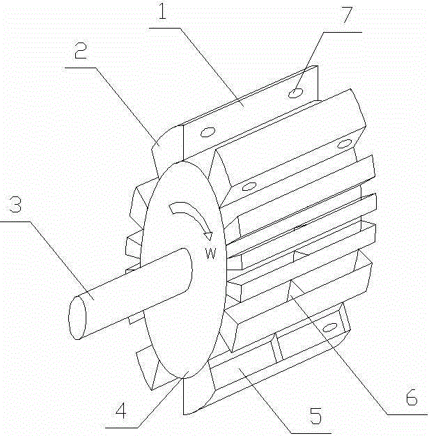
[0017] Such as figure 1 Shown, bucket type wave engine comprises rotor 4 and bucket 2. The rotor 4 is cylindrical or circular, and the two ends of the rotor shaft 3 on the rotor 4 are installed on two floating devices suspended on rivers or oceans through bearings. The floating device can be a ship or other floating objects, as long as the floating object can support the bucket type wave engine.

[0018] The outer circle of the rotor 4 is provided with several water buckets 2 evenly distributed along the circumferential direction, the water buckets 2 are in the structure of a water tank, and the water buckets 2 are arranged along the axial direction of the rotor 4; the openings 5 ​​of several water buckets 2 are sequentially arranged tangentially along the circumference . The 3 axis lines of the rotor shaft are slightly higher than the water...


PUM


Abstract

The invention discloses a water bucket type wave motor. The water bucket type wave motor comprises a rotor and water buckets, wherein the rotor is cylindrical or annular, the water buckets are evenly distributed at the external circle of the rotor in the peripheral direction, each water bucket is of a water tank structure, openings of the water buckets are sequentially arranged along the periphery, the axis of a rotor shaft is slightly higher than the water surface and is parallel with the water surface, and the axis of the rotor shaft is roughly parallel with the bank. A one-way valve is installed on the lateral wall of each water bucket and corresponds to the opening of the corresponding water bucket, water can only enter through each one-way valve, and a water outlet is near the outer side of the bottom surface of each water bucket. Each water bucket is simple in structure, low in manufacturing cost and high in reliability. Due to the fact that the water bucket type wave motor directly collects and utilizes the potential energy of waves and floating force of water to drive the water buckets on the rotor to move for power generation, the wavy energy does not need a middle conversion procedure, and the utilization rate is high. If the geometric size of each water bucket is designed to be small, small broken waves can also be utilized.

Description

technical field [0001] The invention relates to a wave engine, in particular to a bucket type wave engine. Background technique [0002] Today, non-renewable energy sources such as oil, coal, and natural gas are facing depletion of reserves, rising prices, and even serious pollution of the earth's environment. The danger of nuclear fission power generation is high, the nuclear waste pollutes the environment and is difficult to deal with, and the raw materials are becoming less and less; it is not feasible to use nuclear fusion energy to generate electricity. However, solar energy and wind energy are renewable energy sources that do not pollute the environment. However, the cost of existing solar energy is too high, and most of the wind generators are in standby or shutdown state, so the utilization efficiency of wind energy is extremely low. [0003] The ocean contains a large amount of energy, including wave energy, tidal energy, ocean temperature difference energy, salt ...

Claims


Application Information

Patent Timeline
Patent Type & Authority Patents(China)
IPC IPC(8): F03B13/14F03B1/02
CPCY02E10/20Y02E10/30
Inventor 李海啸王明渝古亮
Owner CHONGQING UNIV
Why Eureka
Try Eureka