Vibration wave motor

a technology of vibration wave and motor, applied in piezoelectric/electrostrictive/magnetostrictive devices, piezoelectric/electrostriction/magnetostriction machines, electrical apparatus, etc., can solve problems such as speed drop, and achieve the effect of improving speed

Active Publication Date: 2016-01-21
CANON KK
View PDF2 Cites 6 Cited by
  • Summary
  • Abstract
  • Description
  • Claims
  • Application Information

AI Technical Summary

Benefits of technology

[0009]In this connection, it is an object of the present invention to achieve enhancement of the speed by providing a difference between the resonance fre

Problems solved by technology

As described above, there has been a problem that the speed decreases in the case where the difference is present between the maximum amplitudes of the two natural vibration mod

Method used


Image

  • Vibration wave motor
  • Vibration wave motor
  • Vibration wave motor

Examples


first embodiment

[0028]A description is made below of a first embodiment of the present invention.

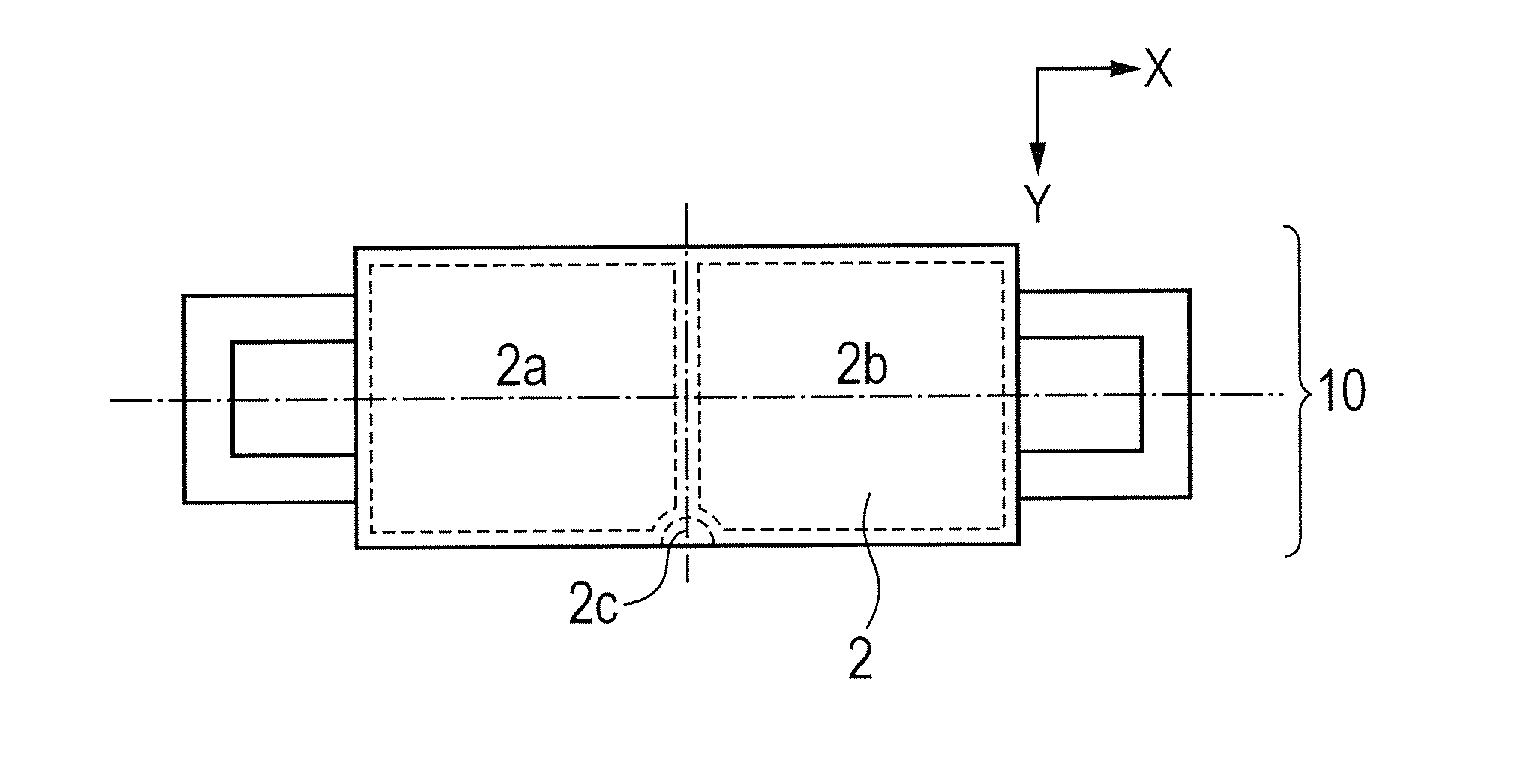
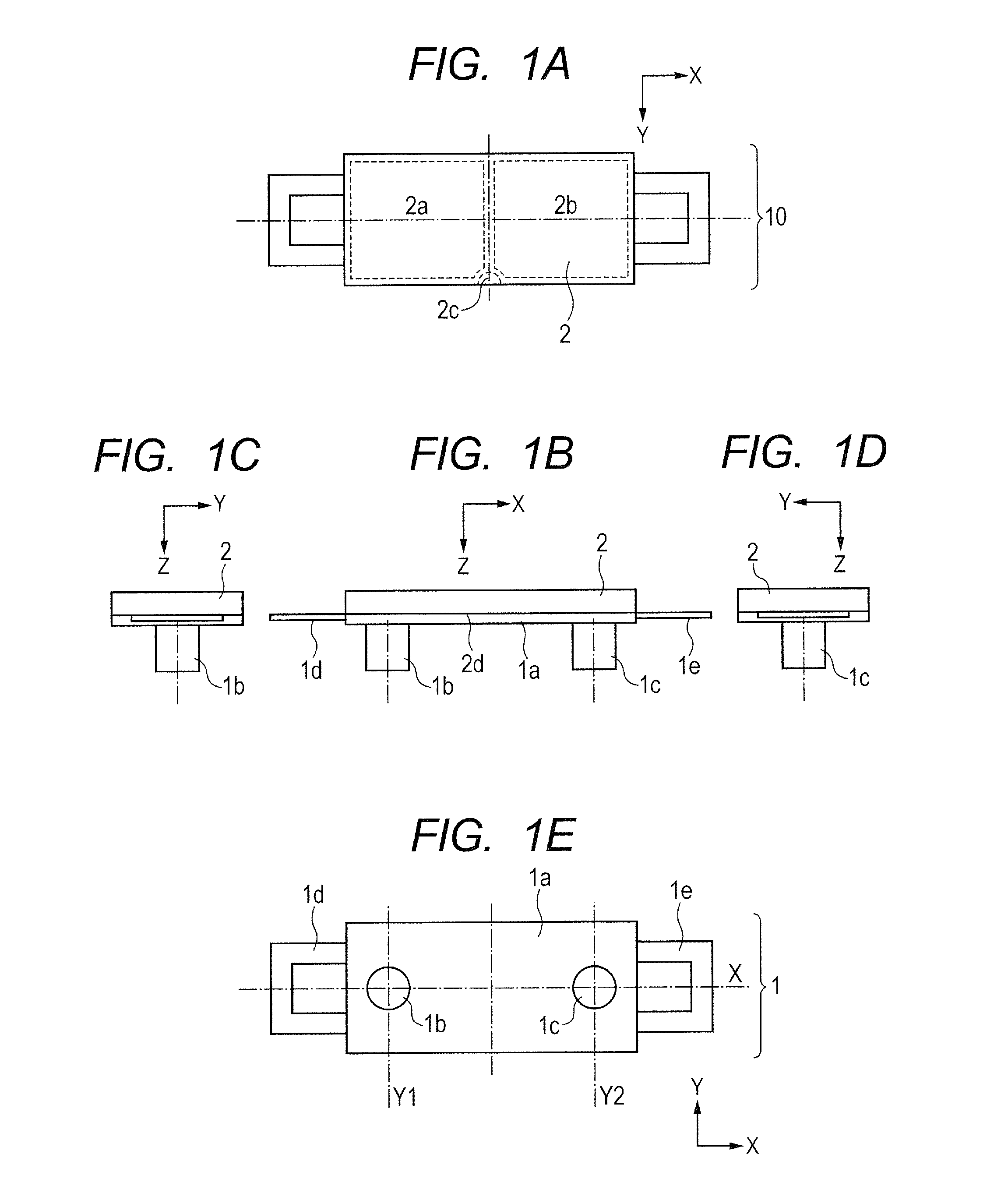
[0029]In this specification, a direction where a vibration plate 1 and a friction member 3, which will be described later, move relatively to each other is defined as an X direction. Moreover, a thickness direction of a flat plate portion 1a, which will be described later, is defined as a Z direction. Furthermore, a direction perpendicular to the X direction and the Z direction is defined, as a Y direction. In the Z direction, an orientation from the vibration plate 1 to the friction member 3 is defined, as a +Z direction, and an orientation from the friction member 3 to the vibration plate 1 is defined as a −Z direction.

[0030]FIGS. 1A to 1E are views for explaining a basic configuration of a vibration wave motor of the first embodiment: FIG. 1A is a plan view; FIG. 1B is a front view; FIG. 1C and FIG. 1D are side views; and FIG. 1F is a bottom view.

[0031]In FIGS. 1A to 1E, the vibration plate 1 include...

second embodiment

[0058]A description made below of a second embodiment for embodying the invention.

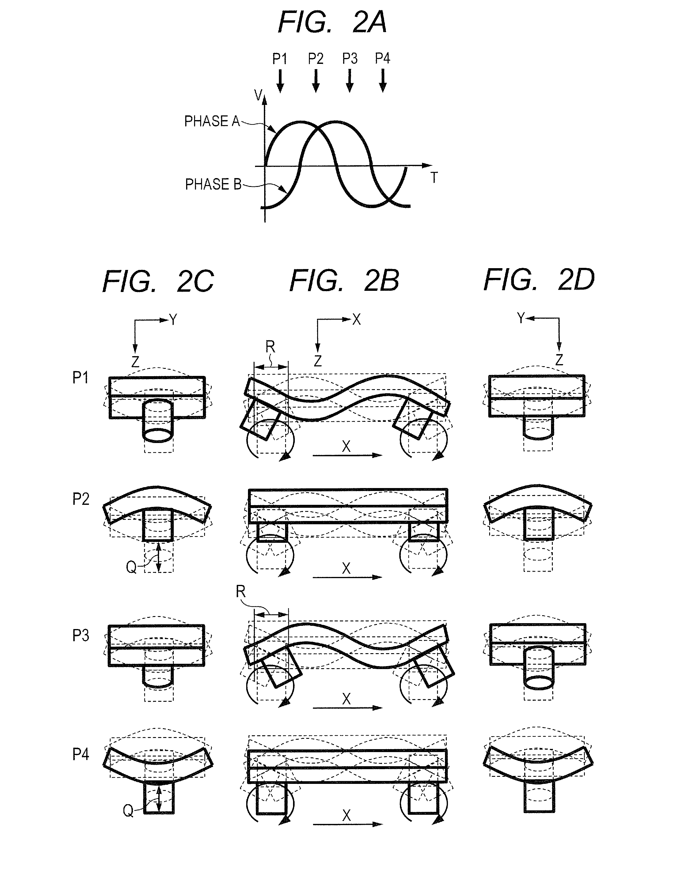
[0059]In the first embodiment, while referring no FIGS. 13A and 13B, the description is made of the case where the first natural vibration mode is the primary natural vibration mode of the bending vibration in the short-side direction of the vibration plate 1, and the second natural vibration mode is the secondary natural vibration mode of the bending vibration in the long-side direction of the vibration plate 1. That is to say, the maximum amplitude A1 generated by the primary natural vibration mode of the bending vibration in the short-side direction becomes larger than the maximum amplitude A2 generated by the secondary natural vibration mode of the bending vibration in the long-side direction. Therefore, the elliptic motion approximate to the circle is generated by increasing the rigidity of the vibration plate 1 in the traveling direction.

[0060]The second embodiment is different from the first emb...

third embodiment

[0067]A description is made below of a third embodiment for embodying the invention.

[0068]In each of the first and second embodiments, the cross-sectional shape of the flat plate portion 1a is formed into the recessed shape, whereby the rigidity in a certain direction is changed to thereby adjust the resonance frequencies f1 and f2 of the two natural vibration modes, and the enhancement of the speed is achieved. In the third embodiment, unlike the first and second embodiments, such rigidity adjusting portions that can increase and decrease the rigidity are provided on the flat plate portion 1a. In such a way, the rigidity in a certain direction is changed to thereby adjust the resonance frequencies f1 and f2 of the two natural vibration modes, and the enhancement of the speed is achieved. Note that the same members as those in the first and second embodiments are illustrated by the same reference numerals. Moreover, a description of the same portions as those of the first and second...


PUM


Abstract

A vibration wave motor includes a vibration plate having a flat plate portion and protruding portions, a piezoelectric element that performs high-frequency vibration, a friction member contacting the protruding portions, and a first natural vibration mode and a second natural vibration mode, which are excited in the vibration plate by the high-frequency vibration, the vibration plate and the friction member moving relatively to each other, maximum amplitude generated on tip ends of the protruding portions by the first natural vibration mode is larger than maximum amplitude generated on tip ends of the protruding portions by the second natural vibration mode, a resonance frequency of the first natural vibration mode is lower than a resonance frequency of the second natural vibration mode, and amplitudes of the first natural vibration mode and the second natural vibration mode in a frequency range at a time of drive substantially coincide with each other.

Description

BACKGROUND OF THE INVENTION[0001]1. Field of the Invention[0002]The present invention relates to a vibration wave motor, and particularly, relates to a vibration wave motor for linear drive, in which an elastic body is formed into a plate shape.[0003]2. Description of the Related Art[0004]Heretofore, vibration wave motors, which have features such as small lightweight, high-speed drive and silent drive, have been employed for a lens barrel of an imaging device. Among them, with regard to a vibration wave motor for linear drive, a vibration wave motor as follows is disclosed in Japanese Patent Application Laid-Open No. 2004-304887.[0005]The vibration wave motor disclosed in Japanese Patent Application Laid-Open No. 2004-304887 is composed of: a vibration plate having a rectangular flat plate portion and protruding portions provided on the flat plate portion; a piezoelectric element that is fixed to the vibration plate and performs high-frequency vibration; and a friction member broug...

Claims


Application Information

Patent Timeline
IPC IPC(8): H02N2/16
CPCH02N2/16H02N2/026H02N2/0015
Inventor NINOMIYA, SHUNSUKE
Owner CANON KK
Why Eureka
Try Eureka