Receiving device, radio clock, and receiving method

a technology of receiving device and radio clock, which is applied in the direction of electric winding, instruments, and horology, can solve the problems of reducing the impedance matching and noise mixing, affecting the reception capability, and affecting the reception signal, so as to improve the receiving capability, prevent the noise from mixing, and reduce the impedance matching

Inactive Publication Date: 2009-10-27
SEIKO EPSON CORP
View PDF10 Cites 1 Cited by
  • Summary
  • Abstract
  • Description
  • Claims
  • Application Information

AI Technical Summary

Benefits of technology

[0007]It is an advantage of the invention to provide a receiving device, a radio clock, and a receiving method capable of solving at least a part of the problems described above.
[0008]A receiving device includes according to a first aspect of the invention includes: an antenna to which a communication signal containing time information is inputted; a ground allowing the antenna to function; a conductive part; a gain characteristics change unit which interrupts continuity between the ground and the conductive part to change the gain characteristics of the antenna; a receiving unit which obtains the time information from the communication signal inputted to the antenna; and a control unit which commands the gain characteristics change unit to interrupt the continuity and commands the receiving unit to obtain the time information. When the time information cannot be obtained from the communication signal inputted to the antenna having a certain type of gain characteristics, the control unit commands the gain characteristics change unit to interrupt the continuity and commands the receiving unit to obtain the time information from the communication signal inputted to the antenna whose gain characteristics have been changed.
[0009]According to this structure, when the time information cannot be obtained from the communication signal inputted to the antenna having the certain type of gain characteristics, the control unit commands the gain characteristics change unit to interrupt the continuity between the ground and the conductive part for changing the certain type of gain characteristics of the antenna, and commands the receiving unit to obtain the time information from the communication signal inputted to the antenna whose gain characteristics have been changed. In this case, the gain characteristics of the antenna can be changed by interruption of the continuity between the ground and the conductive part without the need for providing an electronic component such as attenuator and select switch for changing the gain characteristics disposed on the route of the input signal. Thus, adverse effects such as insertion loss of the select switch, decrease in the impedance matching caused by layout of the attenuator and select switch or the length of the wires, and mixing of noise can be prevented. Accordingly, the receiving capability can be improved without decrease in the receiving quality. Moreover, the size and manufacturing cost of the receiving device can be reduced by eliminating the need for providing the attenuator.
[0010]It is preferable that the gain characteristics change unit has a switch which interrupts the continuity between the ground and the conductive part, and that the antenna has higher gain characteristics when the switch is under the non-conductive condition than those when the switch is under the conductive condition.
[0011]According to this structure, the antenna has higher gain characteristics when the switch is under the non-conductive condition. Thus, the effect of insertion loss of the switch can be further reduced.
[0012]It is preferable to further include an electric field intensity measuring unit which measures electric field intensity of the communication signal. In this case, it is preferable that the control unit commands the gain characteristics change unit to interrupt the continuity by referring to the measured electric field intensity.

Problems solved by technology

In this case, distortion of the receiving signals is caused due to saturation of an amplifier included in the wave clock.
In this case, insertion loss of the select switch is produced, and adverse effects such as decrease in the impedance matching and mixing of noise are caused depending on the layout of the attenuator and select switch and the length of the wires.
As a result, receiving quality is lowered.
Moreover, the necessity for providing the attenuator appropriate for high frequency inside the mobile communication device increases the manufacturing cost and size of the mobile communication device.

Method used


Image

  • Receiving device, radio clock, and receiving method
  • Receiving device, radio clock, and receiving method
  • Receiving device, radio clock, and receiving method

Examples


first embodiment

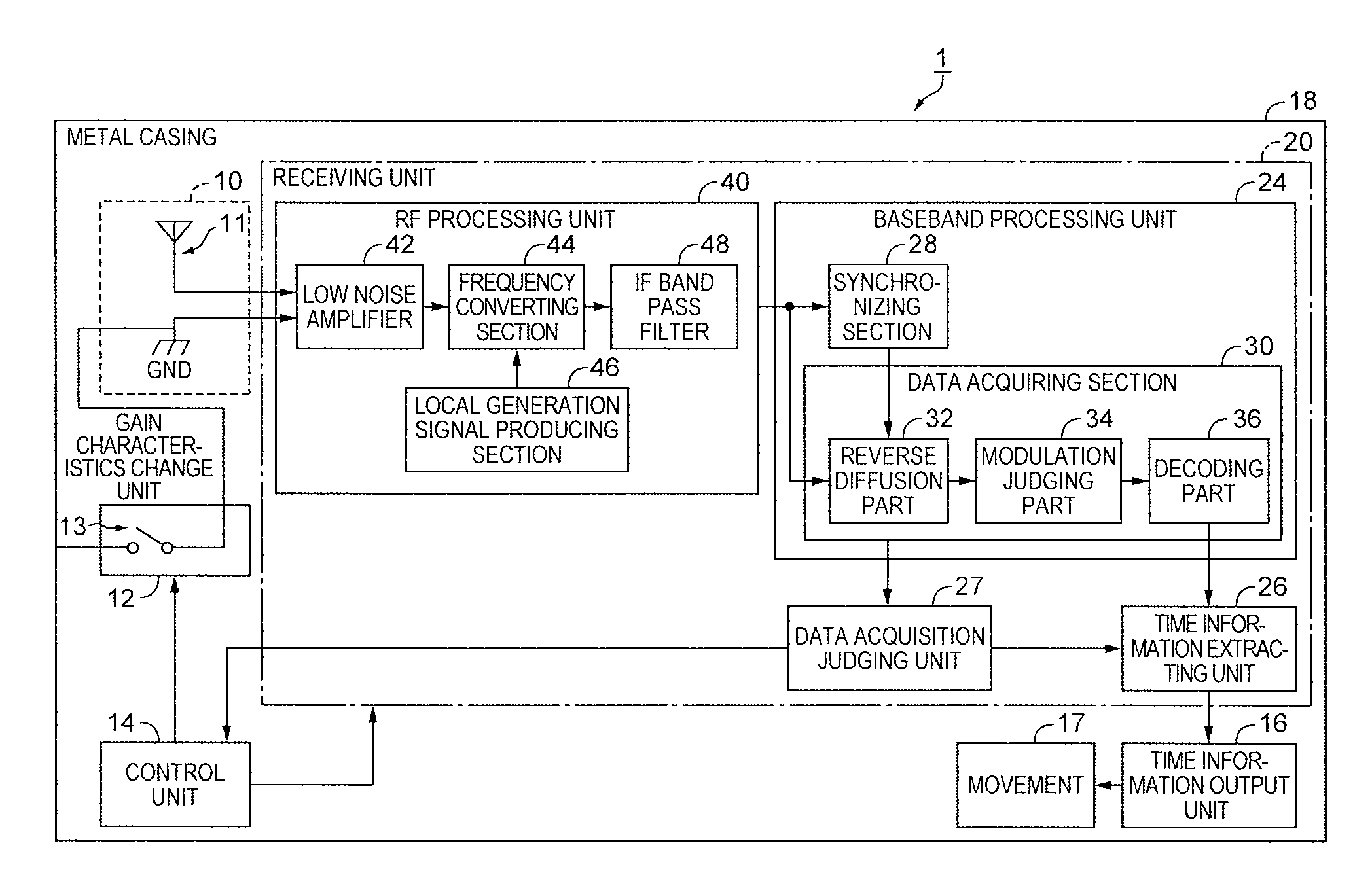
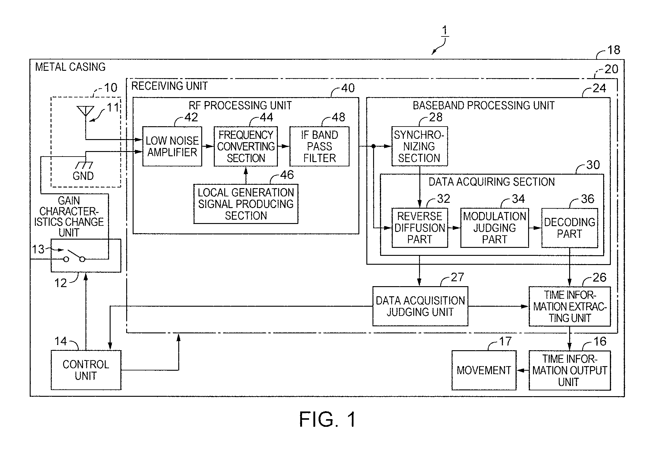
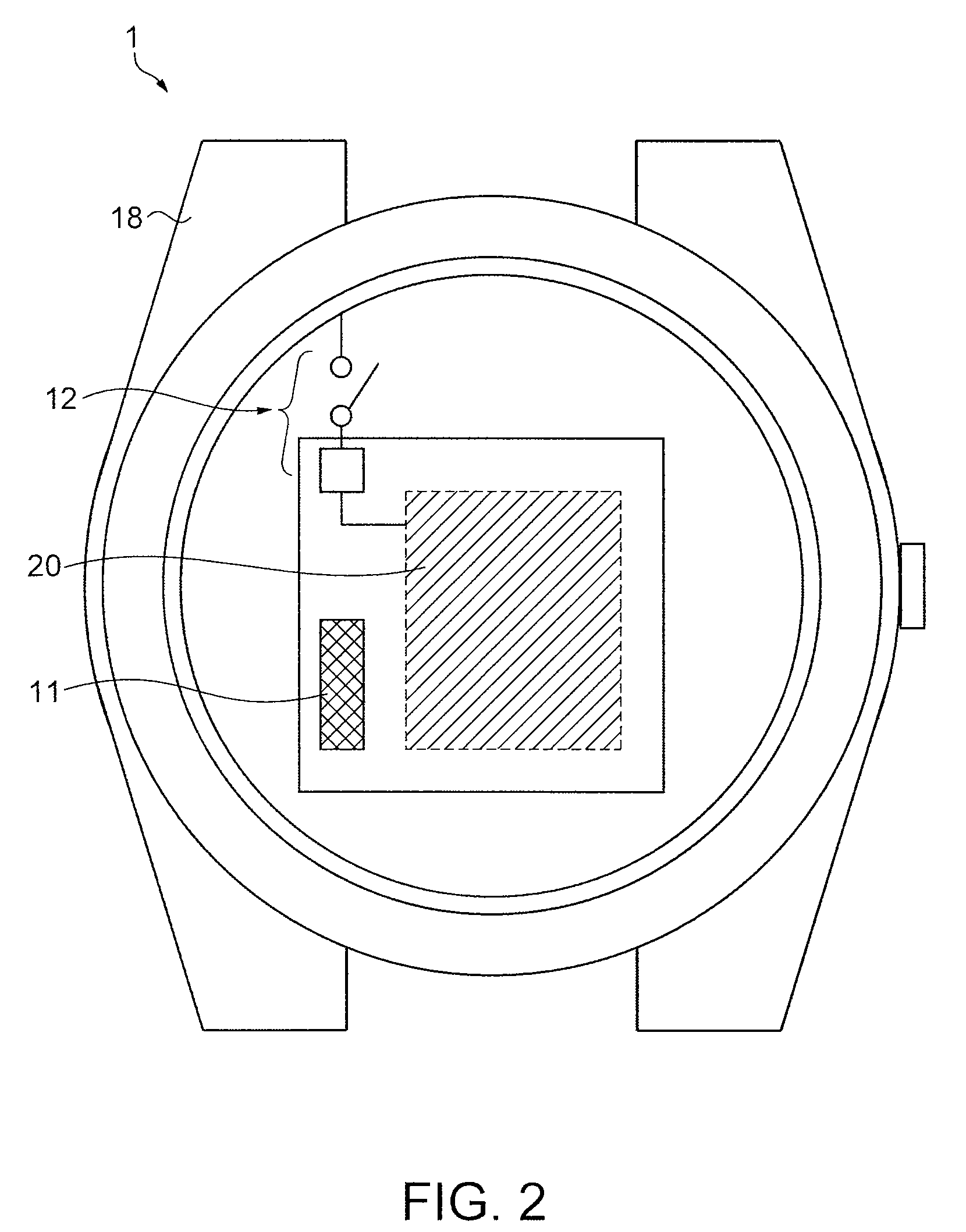
[0032]FIG. 1 is a block diagram showing a structure of a radio clock 1 according to a first embodiment. FIG. 2 is a plan view illustrating a part of the interior of the radio clock 1. The radio clock 1 includes a receiving device which obtains standard time information contained in radio waves in an extremely short wave band transmitted after CDMA modulation, and displays accurate time corrected based on the standard time. More specifically, the radio clock 1 includes an antenna unit 10, a gain characteristics change unit 12, a control unit 14, a receiving unit 20, a time information output unit 16, a movement 17, and a metal casing 18. In these components, the antenna unit 10, the gain characteristics change unit 12, the control unit 14, the receiving unit 20, and the time information output unit 16 constitute the receiving device. According to the first embodiment, the radio clock 1 is a wristwatch shown in FIG. 2, and the metal casing 18 is an external metal case of the wristwatc...

second embodiment

[0052]A second embodiment is now described with reference to FIG. 5. In the following description, similar reference numbers are given to parts similar to those discussed above, and the same explanation is not repeated. According to the first embodiment, the control unit 14 controls interruption of continuity between the ground GND of the antenna unit 10 and the metal casing 18 when time information cannot be extracted from a communication signal. In the second embodiment, an electric field intensity measuring unit 50 for measuring electric field intensity is disposed behind the RF processing unit 40 as shown in the block diagram in FIG. 5. The electric field intensity measuring unit 50 measures electric field intensity in response to a command from the control unit 14, and the information about the measured electric field intensity is transmitted to the control unit 14. When time information cannot be extracted from the communication signal inputted to the antenna 11, the control u...

third embodiment

[0055]A third embodiment is now described with reference to FIG. 6. FIG. 6 is a block diagram showing a structure of the radio clock 1 in the third embodiment. According to the structures in the first and second embodiments, the gain characteristics change unit 12 interrupts continuity between the ground GND of the antenna unit 10 and the metal casing 18 via the switch 13 as a mechanical contact to change gain characteristics. In the third embodiment, however, the continuity is interrupted by an electrical switch. More specifically, the gain characteristics change unit 12 has a diode 121, a capacitor 122, and a resistance 123, and controls continuity between the ground GND of the antenna unit 10 and the metal casing 18 by using direct current control voltage and the diode 121. The continuity may be interrupted by a relay in place of the diode 121.

[0056]According to the third embodiment, the following advantage is offered as well as the advantages (1), (2) and (3) provided in the fir...


PUM


Abstract

A receiving device includes: an antenna to which a communication signal containing time information is inputted; a ground allowing the antenna to function; a conductive part; a gain characteristics change unit which interrupts continuity between the ground and the conductive part to change the gain characteristics of the antenna; a receiving unit which obtains the time information from the communication signal inputted to the antenna; and a control unit which commands the gain characteristics change unit to interrupt the continuity and commands the receiving unit to obtain the time information. When the time information cannot be obtained from the communication signal inputted to the antenna having a certain type of gain characteristics, the control unit commands the gain characteristics change unit to interrupt the continuity and commands the receiving unit to obtain the time information from the communication signal inputted to the antenna whose gain characteristics have been changed.

Description

CROSS-REFERENCES TO RELATED APPLICATIONS[0001]This application claims priority to Japanese Patent Application No. 2007-206208, filed Aug. 8, 2007, whose teachings are incorporated herein by reference.BACKGROUND[0002]1. Technical Field[0003]The present invention relates to a receiving device, a radio clock, and a receiving method for receiving communication signals containing time information.[0004]2. Related Art[0005]A radio clock which displays accurate time information by receiving time signals transmitted on radio waves is designed to receive standard radio waves in a long wave band transmitted from a ground base station, or time signals in an extremely short wave band transmitted from a GPS (global positioning system) satellite. Also, a radio clock proposed in recent years as in JP-A-2000-321383 receives time signals contained in radio waves in an extremely short wave band modulated by CDMA (code division multiple access) before transmission and obtains accurate time for the pur...

Claims


Application Information

Patent Timeline
Patent Type & Authority Patents(United States)
IPC IPC(8): G04C11/02H01Q1/12G04C9/00G04G5/00G04R20/16G04R60/12
CPCG04G21/04G04R20/16G04R60/10
Inventor IRIE, MICHIO
Owner SEIKO EPSON CORP
Why Eureka
Try Eureka