
In-vehicle lift mechanism

a technology of lifting mechanism and vehicle, which is applied in the field of recreation vehicles, can solve the problems of adding prohibitive cost and weight to the vehicl

Active Publication Date: 2009-11-03
LIPPERT COMPONENTS MFG INC
View PDF4 Cites 18 Cited by
  • Summary
  • Abstract
  • Description
  • Claims
  • Application Information

AI Technical Summary

Benefits of technology

"The present invention provides a lift mechanism for raising and lowering a platform in an interior of a recreational vehicle. The lift mechanism includes a frame, a drive unit, a support member supporting the platform, and an elongated flexible member having a first end linked to the drive unit and a second end fixed relative to the frame. The flexible member is directed through at least one turn by at least one guide member engaging the flexible member. The drive unit drives the first end of the flexible member to adjust the height of the support member. The flexible member can include multiple elongated segments, each segment having a first end coupled together with the first ends of the other segments and a second end coupled to the vehicle. The flexible member can also include a leader segment extending between a rotatable spindle of the drive unit and the first ends of the elongated segments. The invention provides a recreational vehicle with a vertical lift mechanism in its interior, which raises and lowers a platform using an elongated flexible member having a first end linked to a drive unit and a second end linked to a fixed member, at least one guide member engaging the flexible member between the first and second ends to direct the flexible member through at least one turn. The technical effects of the invention include improved access to the interior of a recreational vehicle, improved mobility for people with disabilities, and increased flexibility for cargo carrying."

Problems solved by technology

Slide out room assemblies can add prohibitive cost and weight to a vehicle such that other methods must be employed to increase interior seating and like space.

Method used


Image

  • In-vehicle lift mechanism
  • In-vehicle lift mechanism
  • In-vehicle lift mechanism

Examples


Embodiment Construction

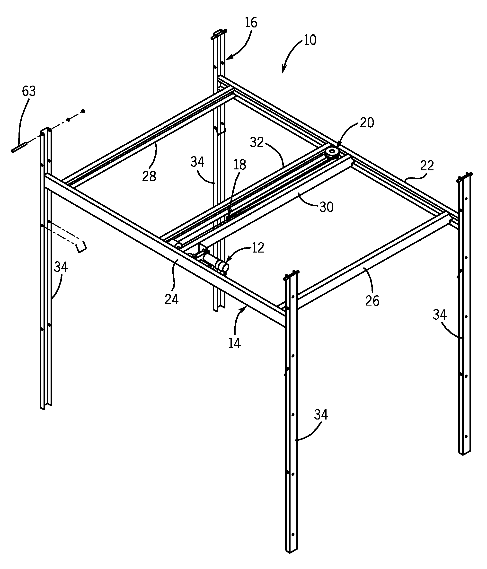
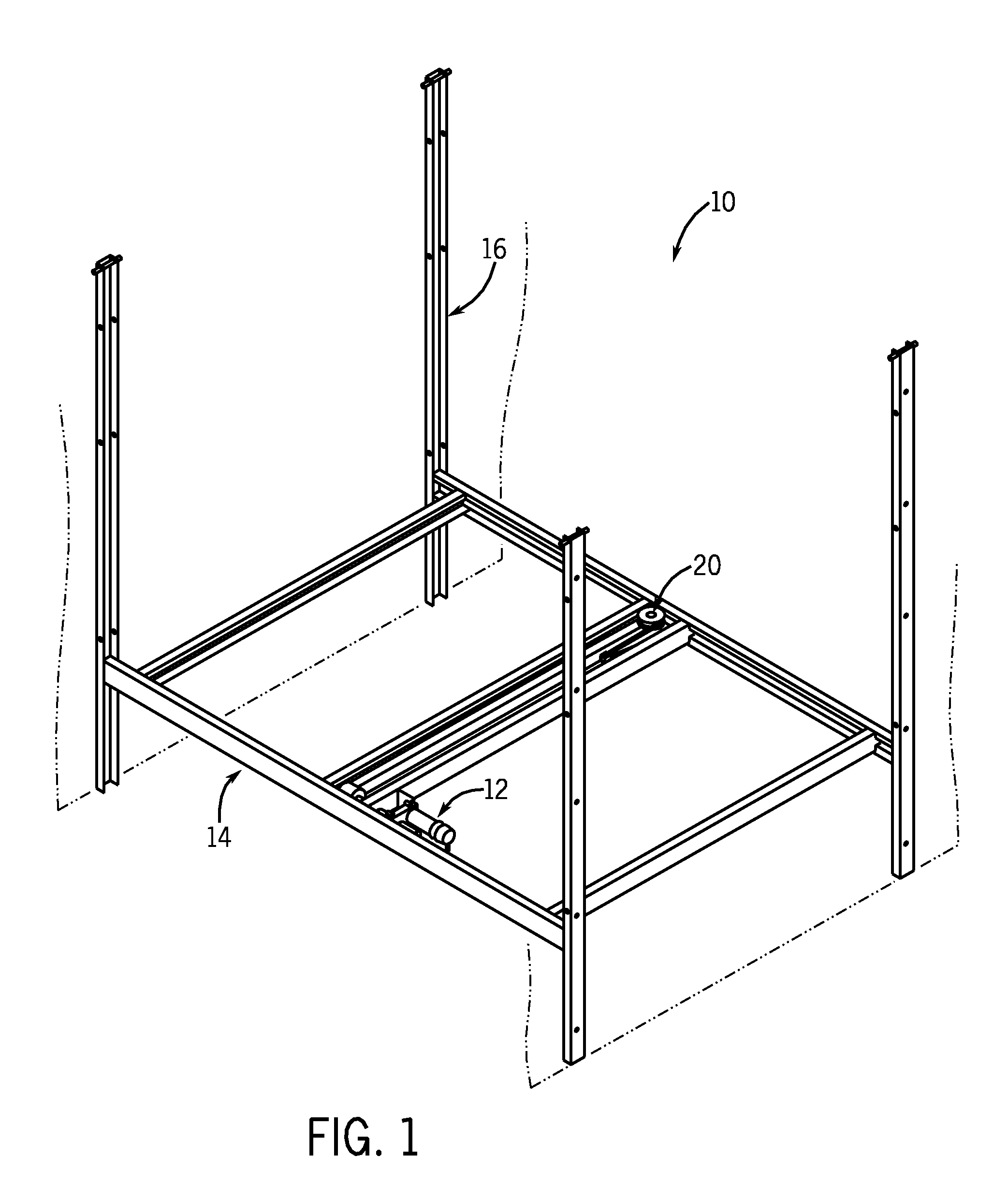
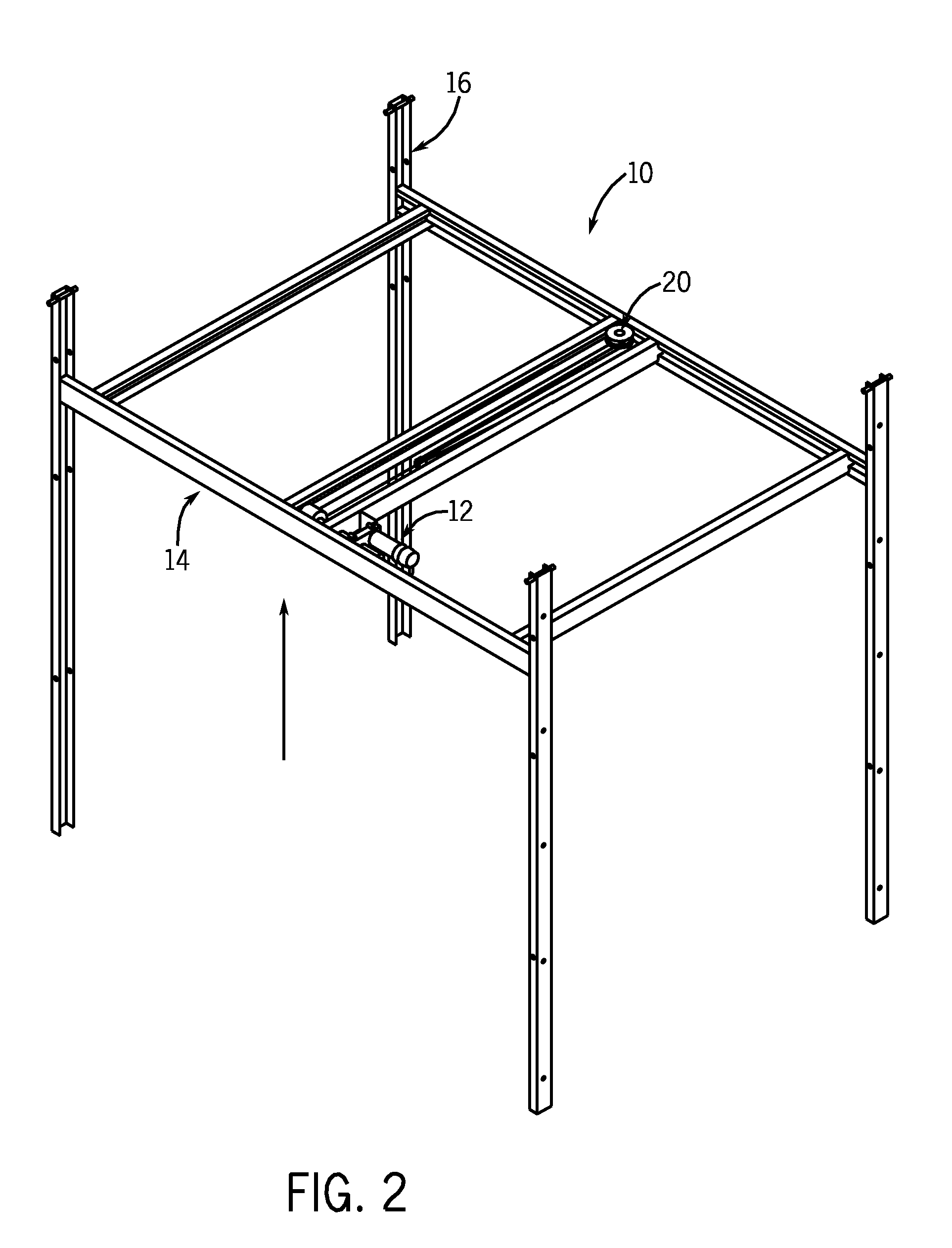
[0024]Although not shown in the drawings, the present invention is preferably used in a passenger vehicle, such as a tow-along trailer or self-propelled (motorhome) recreational vehicle. The lift mechanism 10 shown in FIGS. 1-3 can be advantageously used to vertically elevate a bed or other apparatus for sitting or laying on, and thereby clear floor space in the interior of the vehicle. It could also be positioned straddling a pullout couch to create two beds when the couch is pulled out and the movable platform is lowered to a position spaced below the ceiling and spaced above the couch bed. The lift mechanism 10 is shown in its lowered position in FIG. 1 and shown elevated in FIG. 2. The lift mechanism 10 can be mounted within an extendable and retractable slide-out section of the vehicle to provide further space-saving benefits. Such slide-out sections are well known to have a floor, ceiling, upright end wall and two upright side walls, which form a part of the vehicle exterior w...


PUM


Abstract

The invention provides a vertical lift mechanism (10) for a bunk bed within a recreational vehicle. The mechanism includes a lateral support assembly (14) that travels up and down in an upright frame assembly (34). The lifting force is provided by a drive unit (12) mounted to the support assembly (14) that winds and unwinds a flexible member (18) through a guide arrangement (68, 70, 72, 74, 76, 78, 80, 82) mounted to the support assembly (14). The flexible member (18) is preferably an assembly of cables, more preferably four primary cables (52, 54, 56, 58) each having one end attached to the ceiling of the vehicle and their opposite ends coupled together and linked to a leader cable (50) which is wound about the drive spindle (44). The primary cables (52, 54, 56, 58) travel around the guides (68, 70, 72, 74, 76, 78, 80, 82), which can be an arrangement of single and double sheaves or pulleys, to translate the winding force to vertical forces that raise or lower the support assembly (14).

Description

CROSS-REFERENCE TO RELATED APPLICATION[0001]Not applicable.STATEMENT OF FEDERALLY SPONSORED RESEARCH OR DEVELOPMENT[0002]Not applicable.BACKGROUND OF THE INVENTION[0003]1. Technical Field[0004]The present invention relates to recreational vehicles, and more particularly to lifting mechanisms for raising and lowering furniture within the interiors of such vehicles.[0005]2. Description of the Related Art[0006]In order to increase the available interior space of recreational vehicles or trailers, slide-out sections, such as rooms or closets, can be made integral with the structure of the vehicle or trailer. These slide-out sections usually include a floor, a roof, an end wall and one or more side walls. In the retracted position the roof, floor and side walls are typically inside the vehicle, concealed from exterior view, and the end wall forms a portion of the vehicle's exterior side wall. During transit, these sections are retracted and stored in the interior of the vehicle, with the...

Claims


Application Information

Patent Timeline
Patent Type & Authority Patents(United States)
IPC IPC(8): A47C17/64B60J7/00
CPCB60P3/36B60P1/02
Inventor HOLMES, JAMES K.YODER, DOUGLAS J.PETER, GARY D.
Owner LIPPERT COMPONENTS MFG INC
Learn More