Method of operating an internal combustion engine in an engine warm-up phase

a technology of internal combustion engine and engine heat, which is applied in the direction of electrical control, process and machine control, instruments, etc., can solve the problems of poor heating capability, inability to compensate the lack of heating heat otherwise, and inability to achieve the effect of heating heat release, optimized introduction of heat into the coolant circuit, and high heat releas

Inactive Publication Date: 2009-11-03
DAIMLER AG
View PDF13 Cites 4 Cited by
  • Summary
  • Abstract
  • Description
  • Claims
  • Application Information

AI Technical Summary

Benefits of technology

[0009]The introduction of the pilot injection in a plurality of partial quantities, preferably in two partial quantities, leads to an increase of the charge temperature in the combustion chamber, so that a higher combustion temperature can be generated in a subsequent main injection. This increases an effective introduction of heat into a cooling medium of the coolant circuit. Considerably faster heating of the combustion chamber wall is achieved by means of an obtained higher combustion temperature. The presence of the desired combustion temperature within a suitable time is obtained in the context of the invention as a function of the number of partial quantities of the pilot injection. According to the invention, therefore, during the heat-up phase, a release of heat of the fuel injected into the combustion chamber takes place in a targeted manner in terms of time. The switch to the heat-up phase leads to an at least 40% increase in heat being transferred to the coolant circuit. The coolant can be quickly heated in this way. This leads to rapid and adequate heating of the passenger compartment without the need for an additional heater. A fuel post-injection is preferably carried out in an idle speed range. This ensures stable operation of the internal combustion engine during the heat-up phase.
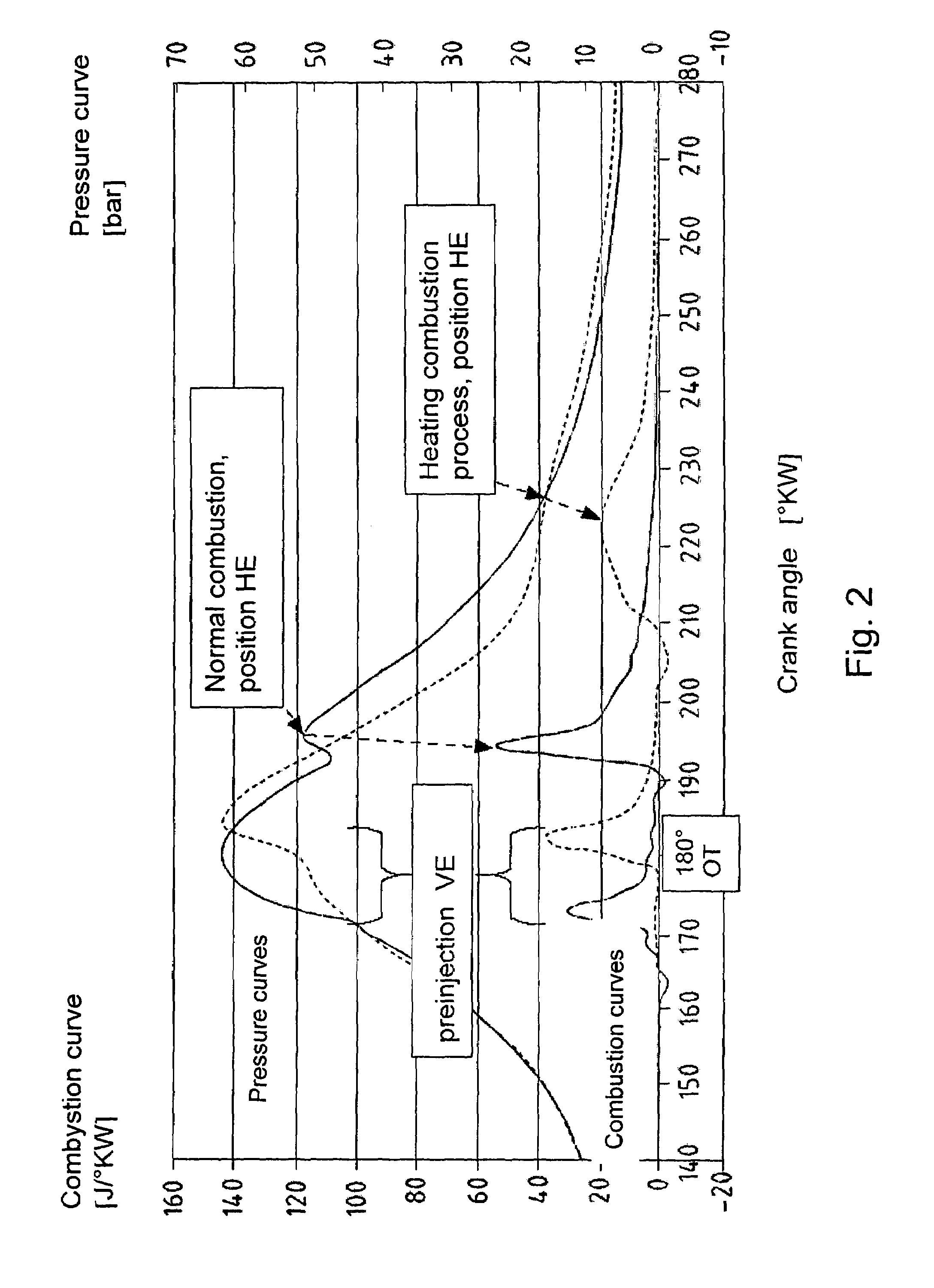
[0010]Preferably, during the heat-up phase, the partial quantities of the pilot injection are introduced into the combustion chamber in a range from 30° CA before top dead center to 5° CA after top dead center, preferably in a range from 25° CA to 5° CA before top dead center. The timing according to the invention of the pilot injections generates a targeted increase of the combustion temperature and therefore an intensified heat transfer through the combustion chamber wall to the coolant. With regard to an introduction of heat into the coolant circuit, as is advantageously aimed at within the context of the invention, it is possible to provide for an optimum time of the heat release of the fuel proportions of the pilot injection.
[0011]During the heat-up phase, the main injection may be carried out in a range from 5° CA to 40° CA, preferably between 15° CA and 25° CA or between 10° CA and 30° CA after top dead center. By carrying out the main injection in the proposed range, a high combustion temperature and a maximum release of heat from the fuel injected into the combustion chamber are obtained at a time, at which rapid heating of the combustion chamber wall is desired. An effective and increased heat transfer to the coolant circuit takes place in this way. In particular in a part-load range after a cold start, it is possible by means of the measures according to the invention to quickly establish a required coolant temperature in order to ensure comfortable heating at extremely low ambient temperatures.
[0014]The effects obtained by the engine-internal measures by means of the injection strategy according to the invention are attributed predominantly to a favorable trade-off between the division of the pilot injection into a plurality of partial quantities, and the hereby optimized time available for the release of heat and the obtained center position of the combustion. The intensified heat introduction into the coolant is further optimized during the heat-up phase depending on the injection times of the pilot and main injections, in particular in the part-load range. A sufficient heating effect can accordingly be realized rapidly in particular after a cold start. The use of an additional heater is therefore not necessary.
[0019]In a further embodiment of the invention, an exhaust gas quantity re-circulated into the combustion chamber by means of the exhaust gas recirculation device during the heat-up phase is greater than a re-circulated exhaust gas quantity in the normal operating mode. In this way, during the heat-up phase, the exhaust gas temperature is increased in relation to that in the normal operating mode. With a higher exhaust gas recirculation rate, it is possible to provide for the generation and transfer of additional heat into the coolant circuit, since the coolant circuit generally extends through an EGR cooler. The re-circulated exhaust gases nevertheless have a higher temperature after the extraction of heat within the EGR cooler than the intake combustion air, and the temperature of the combustion air is therefore increased. Accordingly, an increased amount of heat is generated in a short time in particular after a cold start of the internal combustion engine.

Problems solved by technology

In the operation of modern internal combustion engines, high efficiencies are obtained in combustion, in particular in auto-ignition internal combustion engines, so that less residual heat is present in the exhaust gas of the internal combustion engine than in internal combustion engines of lower efficiency.
Said limited cooling heat quantity leads to a poor heating capability in particular during a warm-up phase of the internal combustion engine after a cold start at low ambient temperatures.
Compensation of the lack of heating heat can otherwise not be obtained.

Method used


Image

  • Method of operating an internal combustion engine in an engine warm-up phase
  • Method of operating an internal combustion engine in an engine warm-up phase
  • Method of operating an internal combustion engine in an engine warm-up phase

Examples


Embodiment Construction

[0023]FIG. 1 shows an internal combustion engine 1 in which a crankshaft 2 is driven via a connecting rod 4 by a piston 5 which is guided in a cylinder 9. Formed in the cylinder 9 between the piston 5 and a cylinder head 10 is a combustion chamber 8 which preferably comprises a recess 6 which is formed in the piston base 7. The piston rod 4 is connected to a crank 3 of the crankshaft 2 which, as it rotates clockwise on a crank circle 11, the combustion chamber 8 is reduced in size, with the air enclosed therein being compressed. The charge exchange in the combustion chamber 8 takes place by means of gas exchange valves (not illustrated) and gas ducts (not illustrated) in the cylinder head 10. When the crank 3 reaches a top dead center 12, also referred to as TDC, the end of the compression is reached, at which point the combustion chamber 8 has the smallest volume and the highest compression pressure and also the highest compression temperature. The momentary position of the piston ...


PUM


Abstract

In a method of operating an internal combustion engine of a motor vehicle during an engine warm-up phase, the engine having a cylinder including a piston defining in the cylinder a combustion chamber, wherein fuel is injected into the combustion chamber in a pilot injection, a main injection and, selectively, a post-injection, and during the heat-up phase of the engine, the center position of the combustion is retarded relative to a center position of the combustion in the normal engine operating mode in order to more rapidly heat the engine and the coolant in the engine cooling circuit for rapid heating of the passenger compartment of the motor vehicle.

Description

[0001]This is a continuation-in-part application of pending International Patent Application PCT / EP2005 / 012612 filed Nov. 25, 2005 and claiming the priority of German Patent Application10 2004 056 004.4 filed Dec. 8, 2004.BACKGROUND OF THE INVENTION[0002]The invention relates to a method of operating an internal combustion engine during the engine heat-up phase depending on the engine coolant temperature, wherein the center of the combustion process is moved back to a retarded position.[0003]In the operation of modern internal combustion engines, high efficiencies are obtained in combustion, in particular in auto-ignition internal combustion engines, so that less residual heat is present in the exhaust gas of the internal combustion engine than in internal combustion engines of lower efficiency. In modern internal combustion engines, therefore, more time passes until a cooling medium of a coolant circuit has warmed up to a temperature required for operating a heater. The generation ...

Claims


Application Information

Patent Timeline
Patent Type & Authority Patents(United States)
IPC IPC(8): F02B3/00
CPCF01P7/167F02D41/005F02D41/061F02D41/086F02D41/405F02D41/403Y02T10/47F05C2251/048Y02T10/44Y02T10/40
Inventor KLINGEBIEL, MATTHIASLUTZE, ROLANDSASS, HEIKO
Owner DAIMLER AG
Why Eureka
Try Eureka