
Shoulder prosthesis assembly

a shoulder joint and assembly technology, applied in the field of shoulder joint assembly, can solve the problems of insufficient technique, insufficient enabling the shoulder joint to operate properly, and the glenoid sphere tends to become unscrewed

Inactive Publication Date: 2009-11-03
DEPUY FRANCE
View PDF38 Cites 41 Cited by
  • Summary
  • Abstract
  • Description
  • Claims
  • Application Information

AI Technical Summary

Benefits of technology

[0013]The object of the invention is to provide a glenoid prosthesis that is arranged in such a manner as to eliminate those various drawbacks.
[0016]Preliminary insertion of the pin in the central bushing of the metaglenoid element makes it possible to provide complete guidance of the glenoid sphere onto the axis of the central bushing of the metaglenoid element. The glenoid sphere screw can then be screwed properly into the metaglenoid bushing without any risk of damaging the threads, thereby almost completely eliminating any risk of needing to have recourse to a second prosthesis.
[0020]These arrangements thus avoid any risk of the screw passing through the metaglenoid element at the end of screw tightening, thus guaranteeing security in the fixing of the metaglenoid element to the glenoid cavity.

Problems solved by technology

When massive rupture occurs of the cuff, only the deltoid remains, and that is insufficient for enabling the shoulder joint to operate properly, which requires a shoulder prosthesis to be implanted.
Unfortunately, it is found that after being in use for a certain length of time, the glenoid sphere tends to become unscrewed.
That technique has turned out to be insufficient.
However, the heads of the screws can pass right through the metaglenoid element at the end of screw tightening if the surgeon cannot feel this end appropriately, since no special retaining means are provided.
Another problem lies in giving the surgeon access to the metaglenoid element, which raises a difficulty with putting the glenoid sphere properly into place on the metaglenoid element.
Access to the metaglenoid element is narrow and relatively difficult, with poor visibility that makes it impossible to tell whether the glenoid sphere screw is exactly on the axis of the metaglenoid bushing.
It results that the surgeon can position the glenoid sphere incorrectly, so that the axial screw of the glenoid sphere is not exactly on the axis of the corresponding hole in the metaglenoid element.
Once the surgeon becomes aware of this faulty insertion, the threads have already become sufficiently damaged to require the entire prosthesis to be replaced.
Not only must two prostheses be used, thus considerably increasing equipment cost, but the time required for the operation is doubled.

Method used


Image

  • Shoulder prosthesis assembly
  • Shoulder prosthesis assembly
  • Shoulder prosthesis assembly

Examples


Embodiment Construction

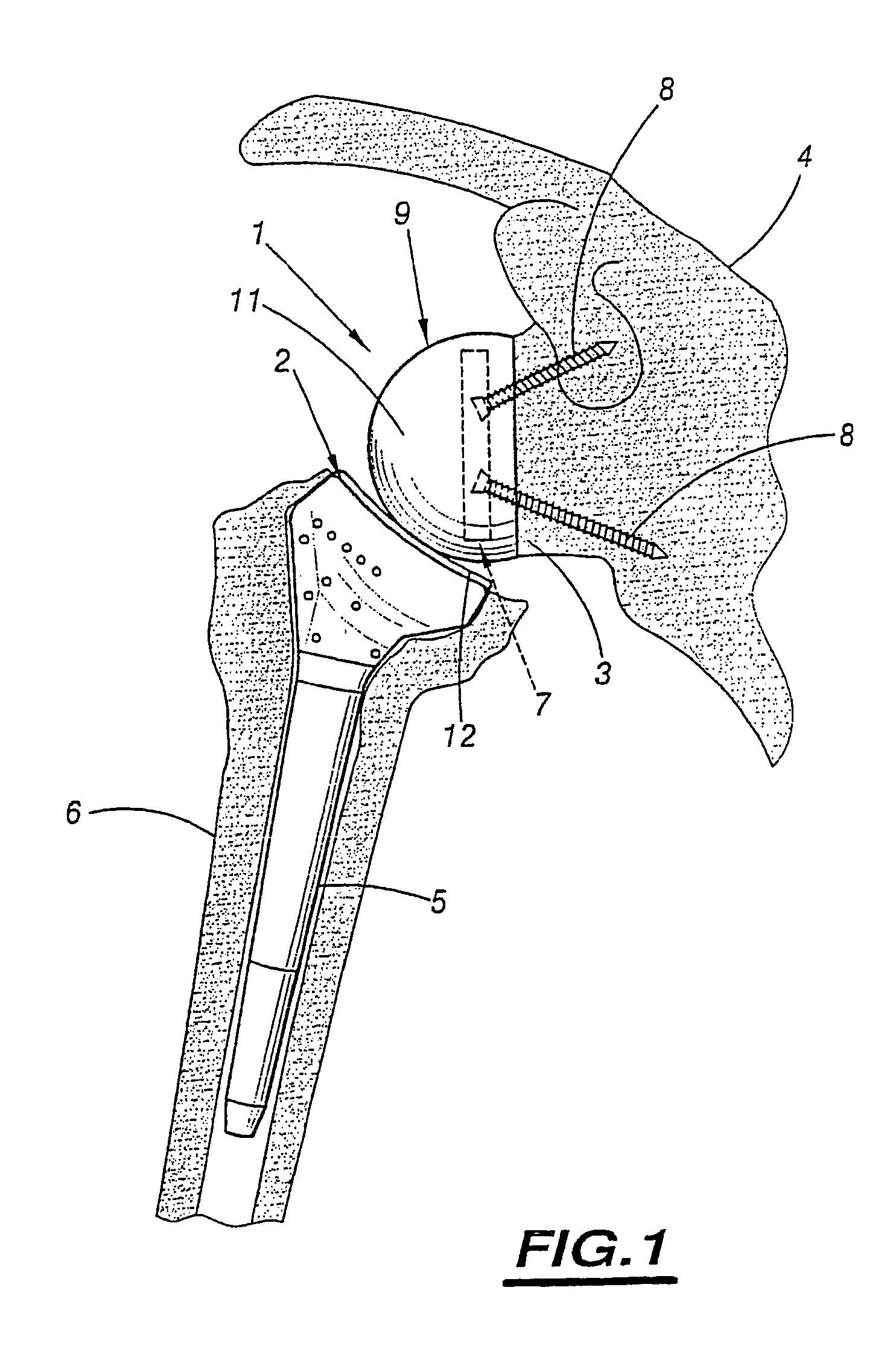
[0029]The total shoulder prosthesis shown in FIG. 1 comprises a glenoid implant 1 and a humeral implant 2, respectively secured to the glenoid cavity 3 of a scapula 4 and in the medullar canal 5 of a humerus 6.

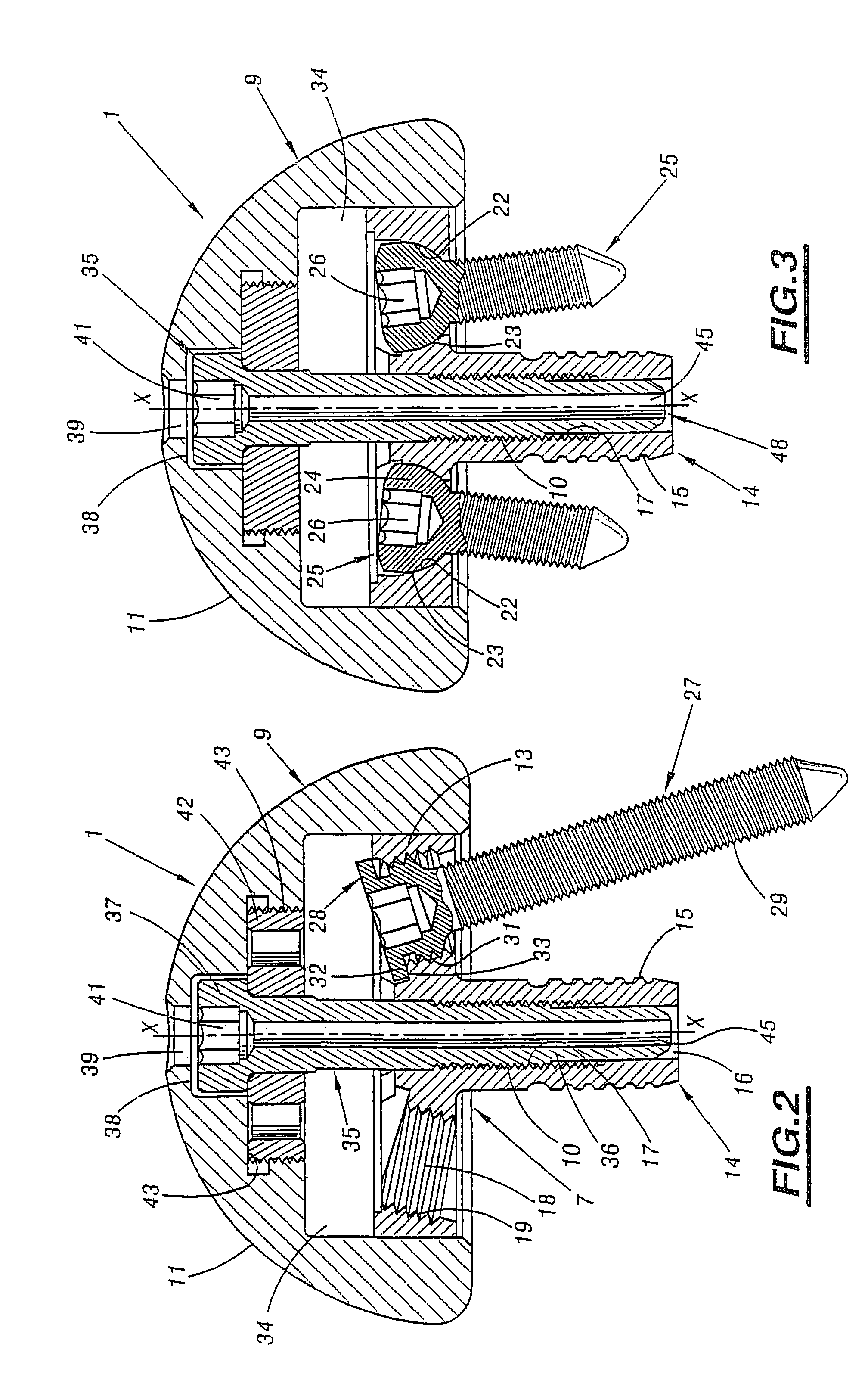
[0030]The glenoid implant 1 comprises both a metaglenoid element 7 formed by a plate 13 (FIGS. 2 to 6) provided with a plurality of screws 8 for anchoring it in the glenoid cavity 3, two of which screws can be seen in FIG. 1, and also a glenoid sphere 9 adapted to be fitted over the metaglenoid element 7.

[0031]The glenoid sphere 9 presents a joint surface 11 which is convex in this embodiment, for co-operating with a complementary surface of a cup 12 of the associated humeral prosthesis 2. In this embodiment, the cup 12 has a concave surface complementary to the convex surface 11.

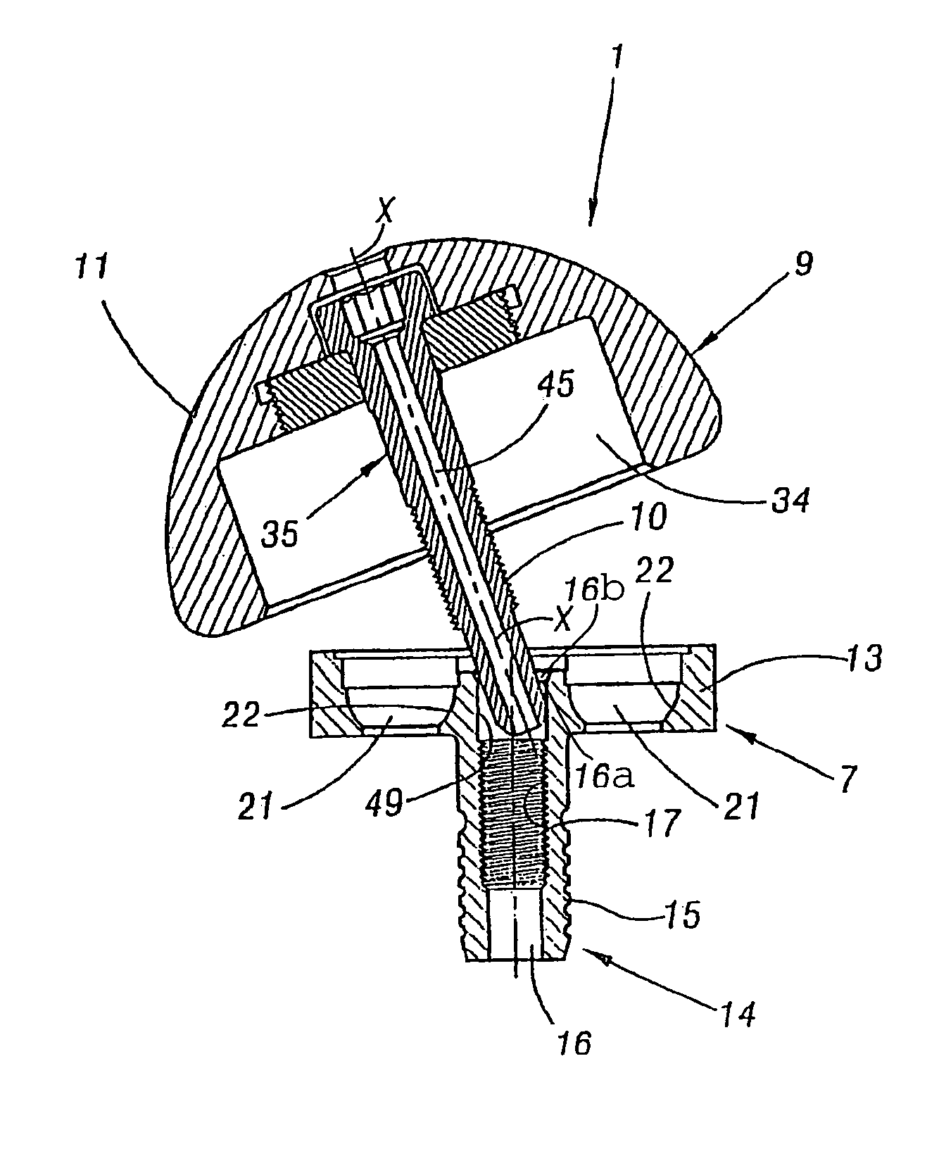
[0032]The plate 13 is preferably conical, being circularly symmetrical about an axis X-X and being fitted with a central tubular adapter or bushing 14 that is preferably integrally formed with the pla...


PUM


Abstract

A shoulder prosthesis assembly includes a metaglenoid element (7) having a plate (13) with a central tubular bushing (14) and members for anchoring it in the glenoid cavity. The assembly also includes a glenoid sphere (9) that fits over the metaglenoid element which has an axial screw that is (35) screwed into the bushing. The glenoid sphere has a member to facilitate installation thereof on the metaglenoid element. The member may include a pin (46) adapted to slide in the tubular bushing (14) and in an axial channel of the screw, so that the glenoid sphere (9) can be screwed into place without any risk of damaging the thread of the screw or the tapping of the bushing.

Description

CROSS REFERENCE TO RELATED APPLICATIONS[0001]This application is a continuation of application Ser. No. 10 / 168,802, filed on Oct. 30, 2002 now U.S. Pat. No. 6,953,478, which is a National Stage of PCT / FR00 / 03539 filed on Dec. 14, 2000, the entire contents of which are hereby incorporated by reference.BACKGROUND OF THE INVENTION[0002]The present invention relates to a shoulder prosthesis assembly of the type comprising a metaglenoid element formed by a plate provided with a central tubular bushing together with members for anchoring in the glenoid cavity, and a glenoid sphere adapted to be fitted over the metaglenoid element. The glenoid sphere is provided with an axial screw that is free to turn relative to the glenoid sphere. This screw is adapted to be screwed into the bushing of the metaglenoid element. The glenoid sphere has a convex joint surface for co-operating with a concave cup of an associated humeral prosthesis.[0003]The invention also provides a prosthesis forming part o...

Claims


Application Information

Patent Timeline
Patent Type & Authority Patents(United States)
IPC IPC(8): A61F2/40A61B17/56A61B17/86A61F2/00A61F2/30A61F2/46
CPCA61F2/4081A61F2/4637A61B17/86A61F2230/0069A61F2/40A61F2/4059A61F2002/30112A61F2002/30143A61F2002/30235A61F2002/30332A61F2002/30372A61F2002/30405A61F2002/30433A61F2002/30507A61F2002/30514A61F2002/30593A61F2002/30604A61F2002/30726A61F2002/30772A61F2002/30774A61F2002/30785A61F2002/30787A61F2002/3079A61F2002/30794A61F2002/3082A61F2002/30828A61F2002/30878A61F2002/4022A61F2002/4062A61F2002/4085A61F2002/4638A61F2002/4677A61F2002/4681A61F2220/0025A61F2220/0033A61F2220/0041A61F2230/0004A61F2230/0017A61B17/8605
Inventor BOUTTENS, DENISDE BUTTET, MICHELCAPON, DIDIERCOLMAR, MICHELNEROT, CECILEVALENTI, PHILIPPEWAHAB, HASSAN
Owner DEPUY FRANCE
Learn More