Method and apparatus for generating an EMI fingerprint for a computer system

a computer system and fingerprint technology, applied in the field of computer system identification techniques, can solve the problems of operating system not providing a mechanism for reading an identifier from a semiconductor chip, time-consuming and burdensome, and chips do not include identifiers

Active Publication Date: 2009-11-03
ORACLE INT CORP
View PDF6 Cites 28 Cited by
  • Summary
  • Abstract
  • Description
  • Claims
  • Application Information

AI Technical Summary

Problems solved by technology

Unfortunately, if the semiconductor chip is integrated within a computer system, this is time-consuming and burdensome because the computer system must be opened to perform a visual inspection of the chip.
Unfortunately, some semiconductor chips do not include identifiers which can be read by an operating system.
Furthermore, some operating systems may not provide a mechanism for reading an identifier from a semiconductor chip.
For example, a government may restrict the computational power of computer systems which can be exported to specified countries.
However, an unscrupulous vendor may modify a computer system that does not violate the export control restriction by substituting a more powerful central processing unit (CPU) into the computer system, and may then attempt to ship the modified computer system to an export-controlled country.
Border inspectors who visually inspect the model number of the computer system may not be able to determine that the computer system has been modified.
Hence, booting up the computer system in order to determine the CPU identifier embedded within the CPU is not necessarily a reliable technique.
Another problem is the possibility that a CPU within the computer system may be substituted with a spy chip, or a piggy-back semiconductor chip may be coupled to the CPU to obtain information from the computer system.
Unfortunately, it is difficult to detect this type of tampering.

Method used


Image

  • Method and apparatus for generating an EMI fingerprint for a computer system
  • Method and apparatus for generating an EMI fingerprint for a computer system
  • Method and apparatus for generating an EMI fingerprint for a computer system

Examples


Embodiment Construction

[0028]The following description is presented to enable any person skilled in the art to make and use the invention, and is provided in the context of a particular application and its requirements. Various modifications to the disclosed embodiments will be readily apparent to those skilled in the art, and the general principles defined herein may be applied to other embodiments and applications without departing from the spirit and scope of the present invention. Thus, the present invention is not limited to the embodiments shown, but is to be accorded the widest scope consistent with the principles and features disclosed herein.

[0029]The data structures and code described in this detailed description are typically stored on a computer-readable storage medium, which may be any device or medium that can store code and / or data for use by a computer system. This includes, but is not limited to, volatile memory, non-volatile memory, magnetic and optical storage devices such as disk drive...


PUM


Abstract

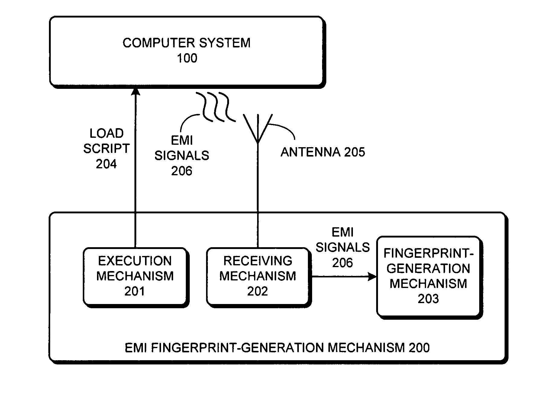
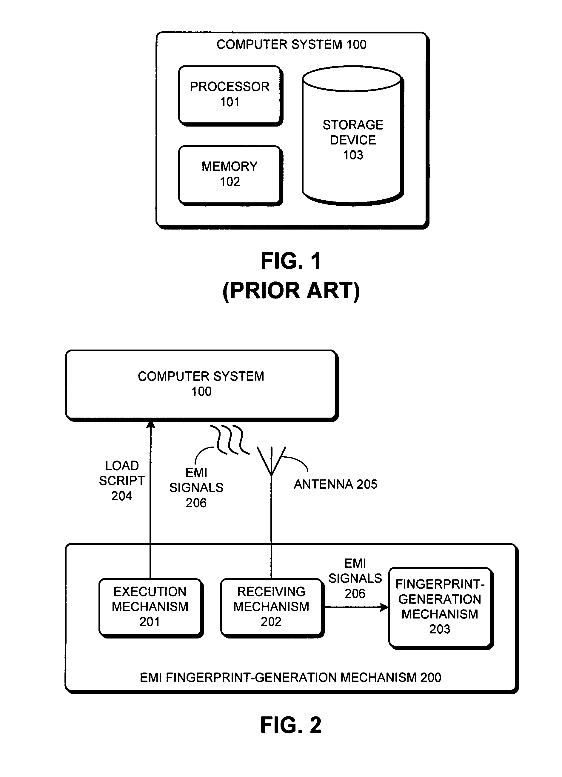
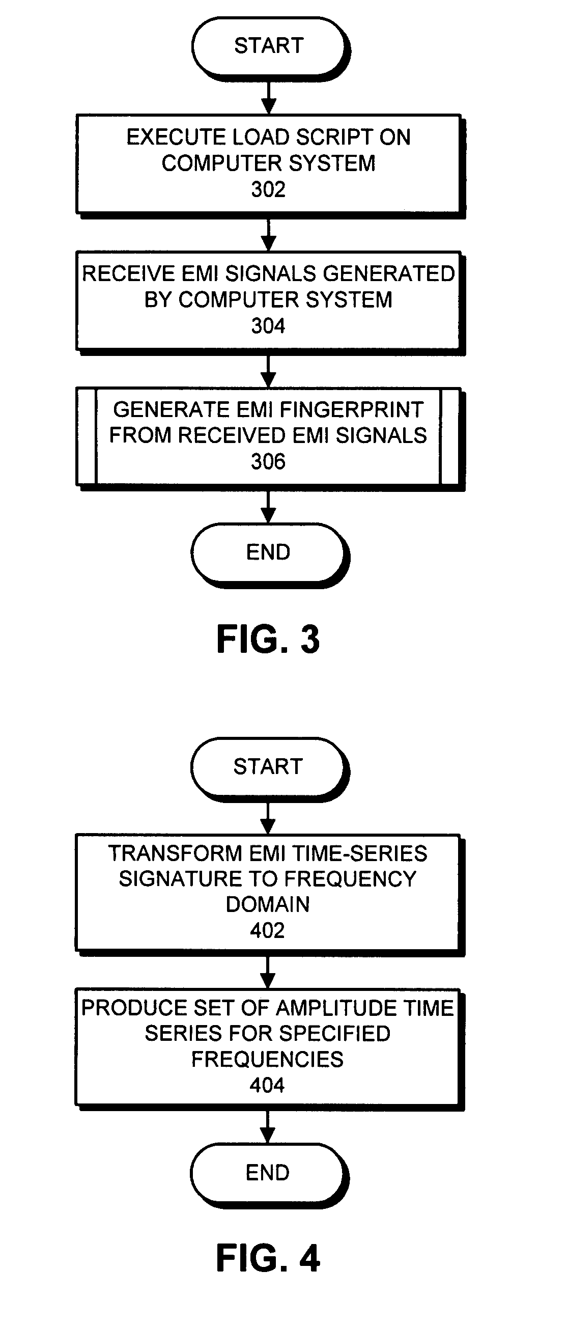
A system that generates an electromagnetic interference (EMI) fingerprint for a computer system is presented. During operation, the system executes a load script on the computer system, wherein the load script includes a specified sequence of operations. Next, the system receives EMI signals generated by the computer system while executing the load script. The system then generates the EMI fingerprint from the received EMI signals.

Description

RELATED APPLICATION[0001]The subject matter of this application is related to the subject matter in a non-provisional application by inventors Kenny C. Gross, Aleksey M. Urmanov, Ramakrishna C. Dhanekula, and Steven F. Zwinger entitled, “Using EMI Signals To Facilitate Proactive Fault Monitoring in Computer Systems,” having Ser. No. 11 / 787,003, and filing date Apr. 12, 2007.BACKGROUND[0002]1. Field of the Invention[0003]The present invention relates to techniques for identifying a computer system. More specifically, the present invention relates to a method and apparatus for generating an EMI fingerprint for a computer system.[0004]2. Related Art[0005]A given semiconductor chip design can be implemented in a number of different versions of the chip. For example, the different versions can include chips with varying speeds and chips with incremental changes to the functionality. Hence, it is often useful to be able to identify the specific version of a semiconductor chip.[0006]One te...

Claims


Application Information

Patent Timeline
Patent Type & Authority Patents(United States)
IPC IPC(8): G06F11/30
CPCG06F21/73G01R31/002Y10T70/5093Y10T70/5257
Inventor GROSS, KENNY C.URMANOV, ALEKSEY M.DHANEKULA, RAMAKRISHNA C.
Owner ORACLE INT CORP
Why Eureka
Try Eureka