

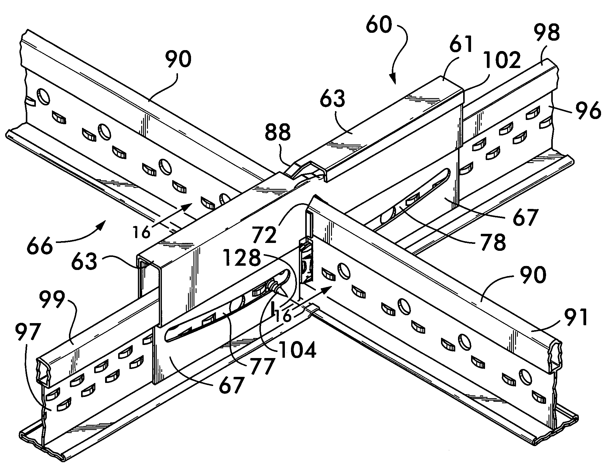
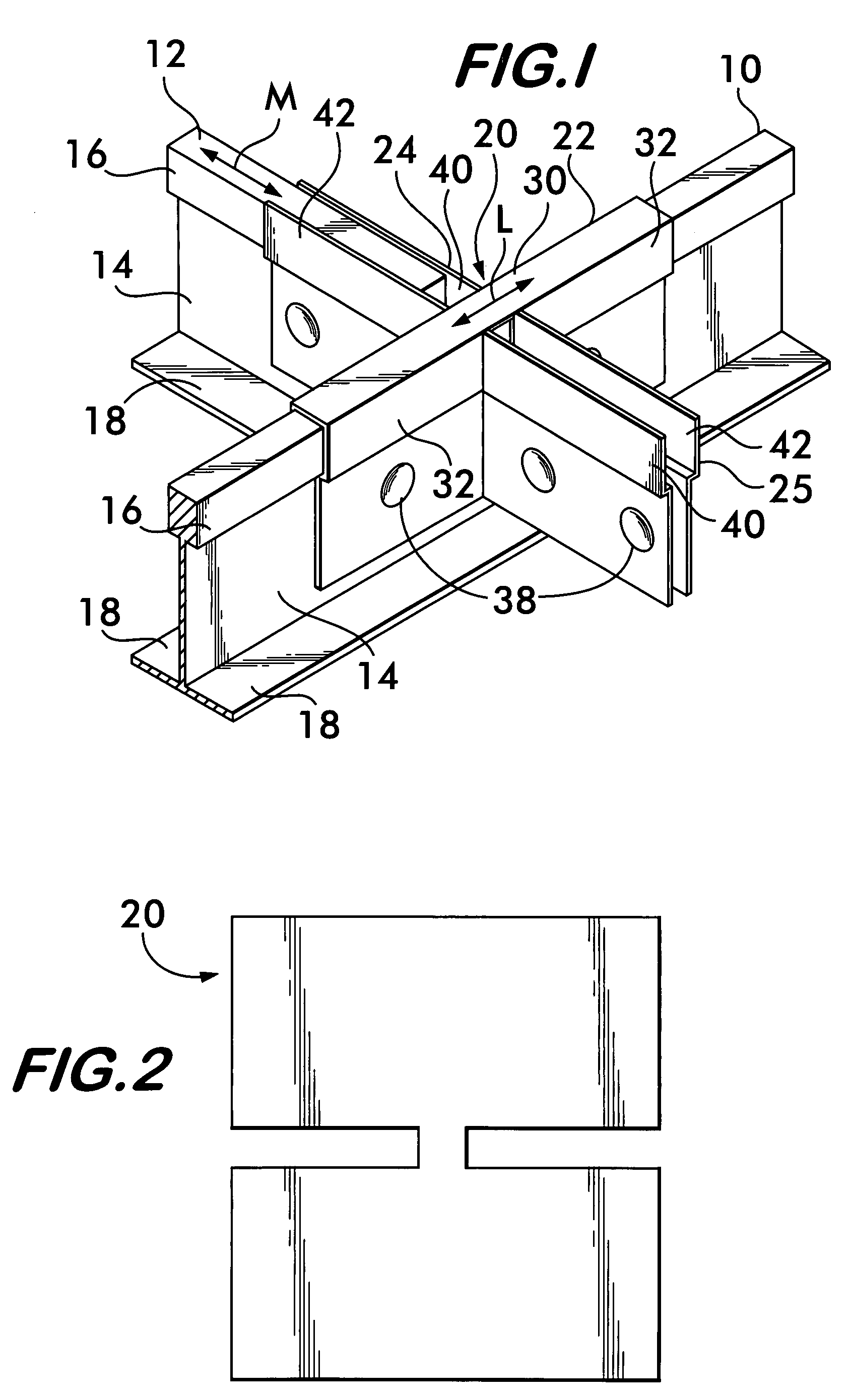
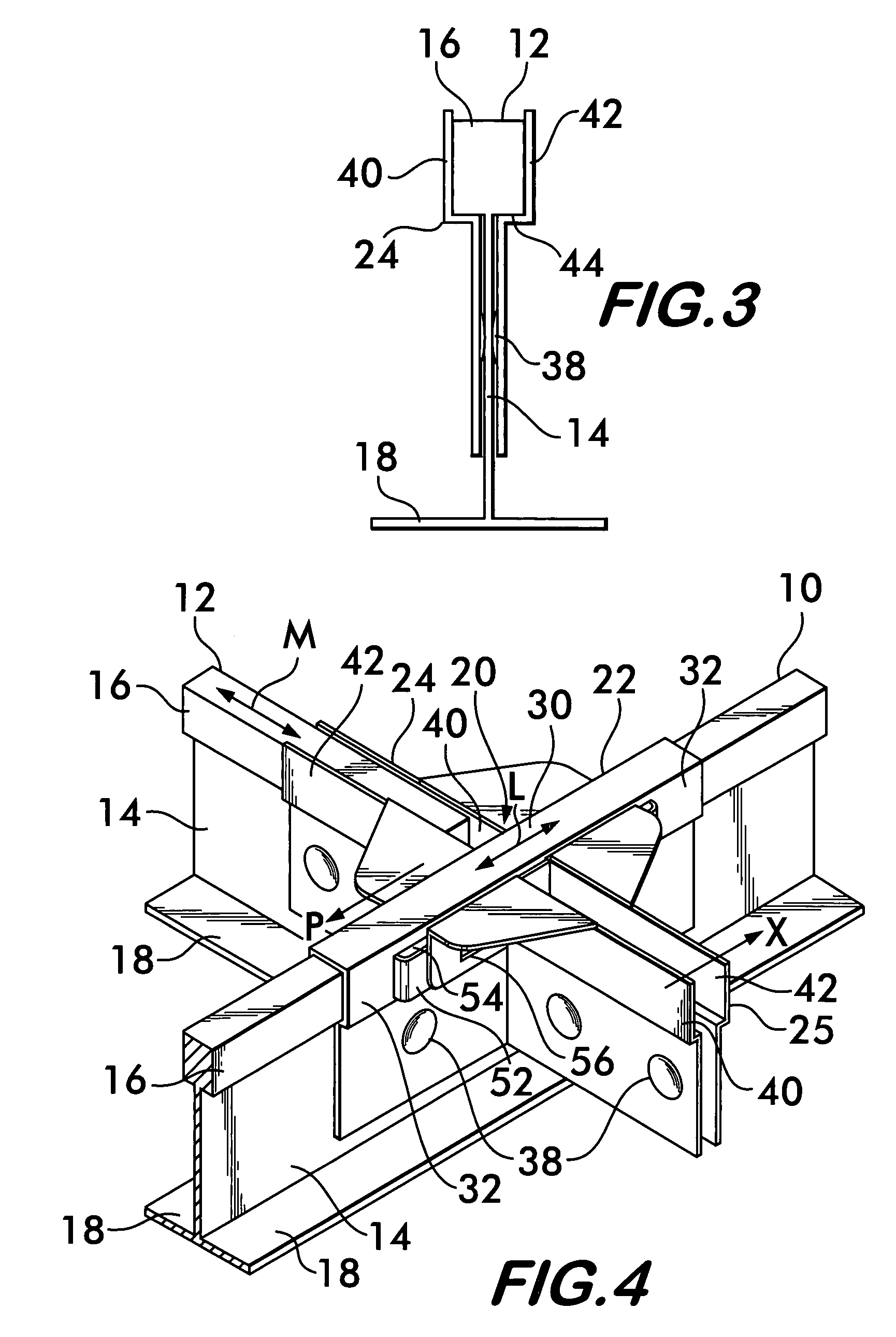
Suspended ceiling grid network utilizing seismic separation joint clips
a grid network and suspended ceiling technology, applied in ceilings, walls, flooring, etc., can solve the problems of inability to use grid members with such wide flanges, affecting the aesthetic appeal of the overall grid network, and reducing the possibility of displacemen
- Summary
- Abstract
- Description
- Claims
- Application Information
AI Technical Summary
Benefits of technology
Problems solved by technology
Method used
Image

Examples
Embodiment Construction
1. The Embodiments of the Joint Clips shown in FIGS. 1 through 11
[0029]The following description of the invention is provided as an enabling teaching of the invention in its best, currently known embodiments. Those skilled in the relevant art will recognize that many changes can be made to the embodiments described while still obtaining the beneficial results of the present invention. It will also be apparent that some of the desired benefits of the present invention can be obtained by selecting some of the features of the present invention without utilizing other features. Accordingly, those who work in the art will recognize that many modifications and adaptations to the present invention are possible and may even be desirable in certain circumstances and are a part of the present invention. Thus, the following description is provided as illustrative of the principles of the present invention and not in limitation thereof, since the scope of the present invention is defined by the...
PUM
 Abstract
Description
Claims
Application Information