
Turbine installation having a connectable auxiliary group

a technology of auxiliary group and turbine, which is applied in the direction of engine starter, engine/propulsion engine ignition, electric generator control, etc., can solve the problem that the braking torque cannot be applied via the main group to the auxiliary group, and achieve the effect of reducing the number of auxiliary group members

Inactive Publication Date: 2009-11-10
ALSTOM TECH LTD
View PDF16 Cites 75 Cited by
  • Summary
  • Abstract
  • Description
  • Claims
  • Application Information

AI Technical Summary

Benefits of technology

[0014]An object of the present invention is to provide a method for starting a turbine installation with a connectable auxiliary group that reduces or avoids one or more disadvantages of the prior art. In particular, the method of the present invention is intended to contribute to the capability to start and / or shut down, in a short time, a turbine installation which is used for electricity generation and has a connectable auxiliary group, with an additional aim of largely avoiding the formation of windage in the auxiliary group. An aim of a further aspect of the invention is to provide an additional degree of freedom for the design of a turbine installation with a connectable auxiliary group, in particular with regard to transient operating states of the installation, such as starting or shutting down the installation.

Problems solved by technology

In particular, no braking torque can be applied via the main group to the auxiliary group when they are decoupled.

Method used


Image

  • Turbine installation having a connectable auxiliary group
  • Turbine installation having a connectable auxiliary group
  • Turbine installation having a connectable auxiliary group

Examples


Embodiment Construction

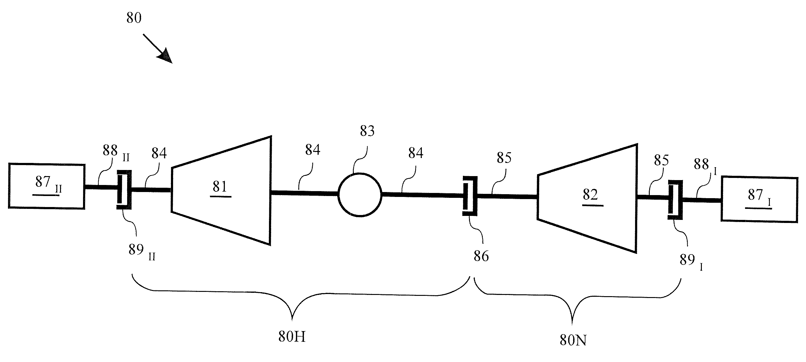
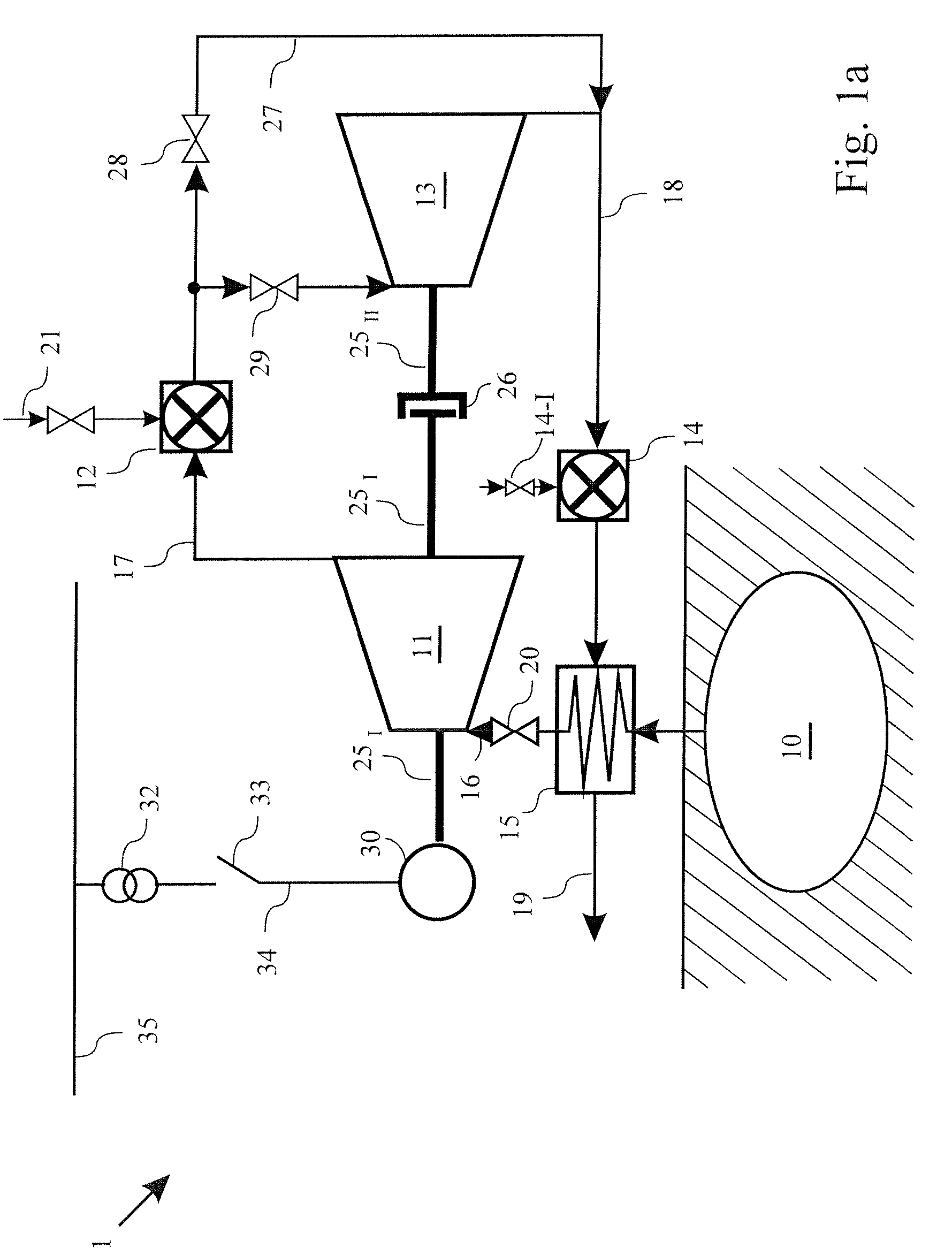
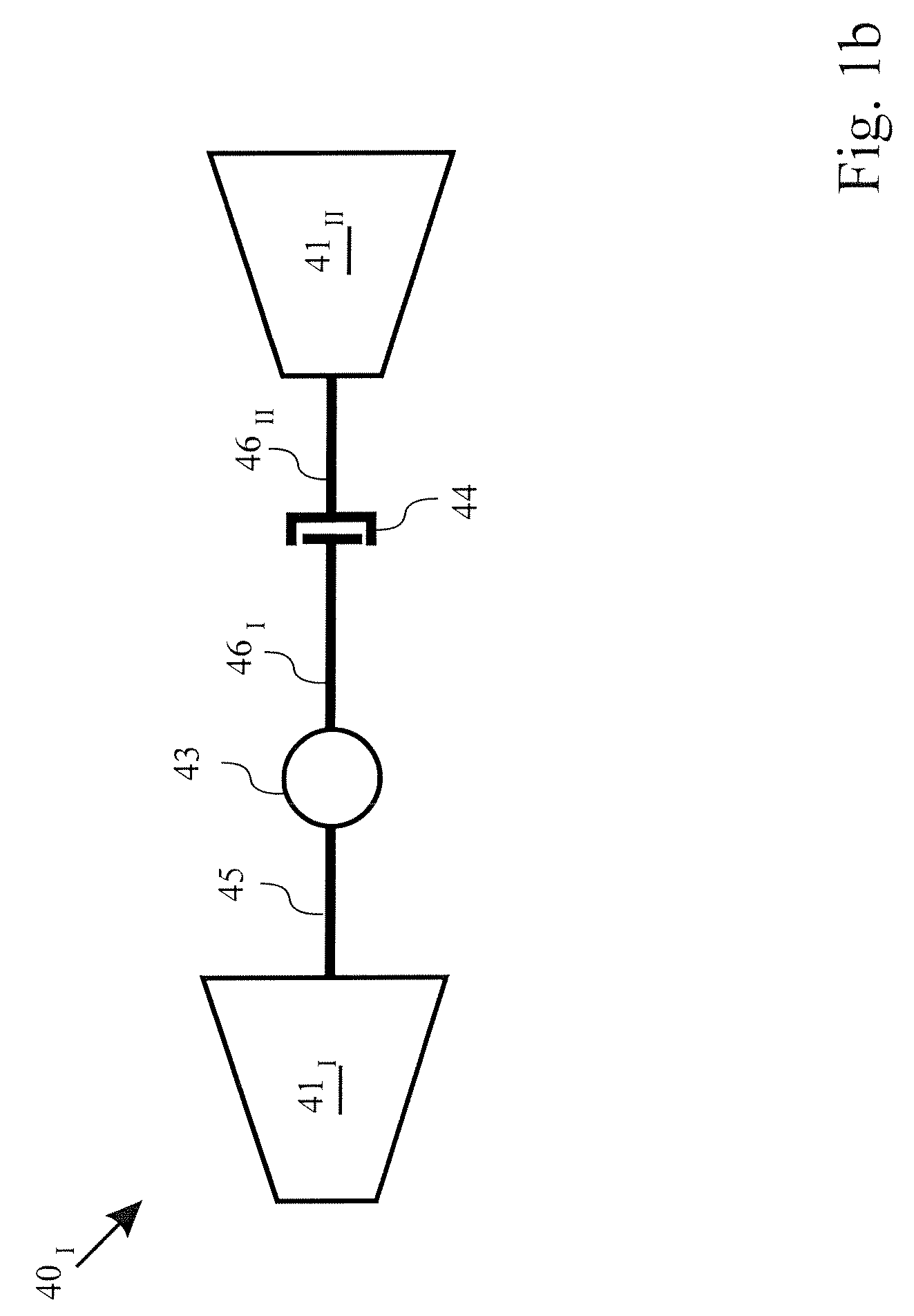
[0062]FIG. 1a shows a schematic illustration of a CAES installation 1 according to the prior art. The CAES installation 1 has a gas reservoir 10 in which a gas, for example air, can be stored under pressure. Furthermore, the CAES installation 1 has a turbine set which, in the embodiment illustrated in FIG. 1a, comprises a first air turbine 11 and a low-pressure turbine 13 connected downstream from the air turbine. The gas reservoir 10, the air turbine 11 and the low-pressure turbine 13 are connected to one another via connection lines 16 and 17. A shut-off valve 20 in order to restrict or shut off the flow from the gas reservoir 10 is arranged in the connection line 16. The low-pressure turbine 13 is then followed by further lines 18 and 19.

[0063]Furthermore, a heat exchanger 15 is connected in the line 16 upstream of the air turbine 11. The fuel-gas / air mixture emerging from the low-pressure turbine 13 is used in the heat exchanger 15 to preheat the air coming from the gas reservoi...


PUM


Abstract

A turbine installation includes a main group and an auxiliary group, wherein the main group has at least one first turbine and a generator connected for drive purposes to the first turbine. The auxiliary group includes at least one second turbine and is connectable to the main group via a coupling. The turbine installation furthermore includes a first braking device configured to apply a braking torque to the auxiliary group when the auxiliary group is decoupled from the main group.

Description

[0001]This application is a continuation of International Patent Application No. PCT / EP2006 / 061182, filed on Mar. 30, 2006, which claims priority to Swiss Patent Application No. CH 00547 / 05, filed Mar. 30, 2005. The entire disclosure of both documents is incorporated by reference herein. The International Patent Application designated the United States and was published in German as WO2006 / 103270 on Oct. 5, 2006.[0002]The present invention relates to a method for starting a turbine installation with a connectable auxiliary group.BACKGROUND[0003]Modern turbine installations which are used for electricity generation in groups of power stations should be capable of being started in as short a time as possible from being stationary to the rated rotation speed in order in this way to ensure that the installation has high operational reliability. Turbine installations in particular which are used to cover a peak load are especially subject to this requirement. In order to cover peak loads...

Claims


Application Information

Patent Timeline
Patent Type & Authority Patents(United States)
IPC IPC(8): F02C7/22
CPCF01D13/00F02C3/10F01D21/006F01D19/00
Inventor HERZOG, MAURUSHIEGEMANN, MICHAEL
Owner ALSTOM TECH LTD
Learn More