
Endolumenal gastric ring with suspended impeding member

a technology of which is applied in the field of endolumenal gastric ring and impeding member for the treatment and control of obesity, can solve the problems of unreliable stapling procedures, inability to adjust, and inability to perform gastric bypass surgery and stapling procedures. to achieve the effect of reducing the risk of surgery, and adjusting the ability to ingest food materials

Inactive Publication Date: 2009-11-10
BERNARD MEDICAL
View PDF26 Cites 49 Cited by
  • Summary
  • Abstract
  • Description
  • Claims
  • Application Information

AI Technical Summary

Benefits of technology

This solution provides a safer, more reliable, and adjustable method for obesity treatment, enabling adjustable food intake and potential medication delivery, reducing invasiveness and complications associated with traditional procedures.

Problems solved by technology

Stapling procedures may be unreliable and in some cases unsafe because the staples may come out or cause perforations and tears in the stomach wall.
Further, the pouch or the outlet formed by the staples may become enlarged over time, thereby making the procedure useless.
Further, gastric bypass surgery and stapling procedures do not generally allow for adjustability in the size of the stomach or stoma once the procedure has been completed.
Gastric band procedures also have several disadvantages, such as band displacement or erosion of the band in the gastric lumen, to name a few.
Such occurrences may cause pain and discomfort to the patient.
A further disadvantage of these related art method and devices is that they generally require complicated surgical procedures.
The invasiveness related to these surgical procedures can cause pain, prolonged recovery, complications, and in some cases may result in death.
Moreover, the procedure can also be technically challenging for the surgeon, and cause great expense to the patient and the healthcare system in general.

Method used


Image

  • Endolumenal gastric ring with suspended impeding member
  • Endolumenal gastric ring with suspended impeding member
  • Endolumenal gastric ring with suspended impeding member

Examples


Embodiment Construction

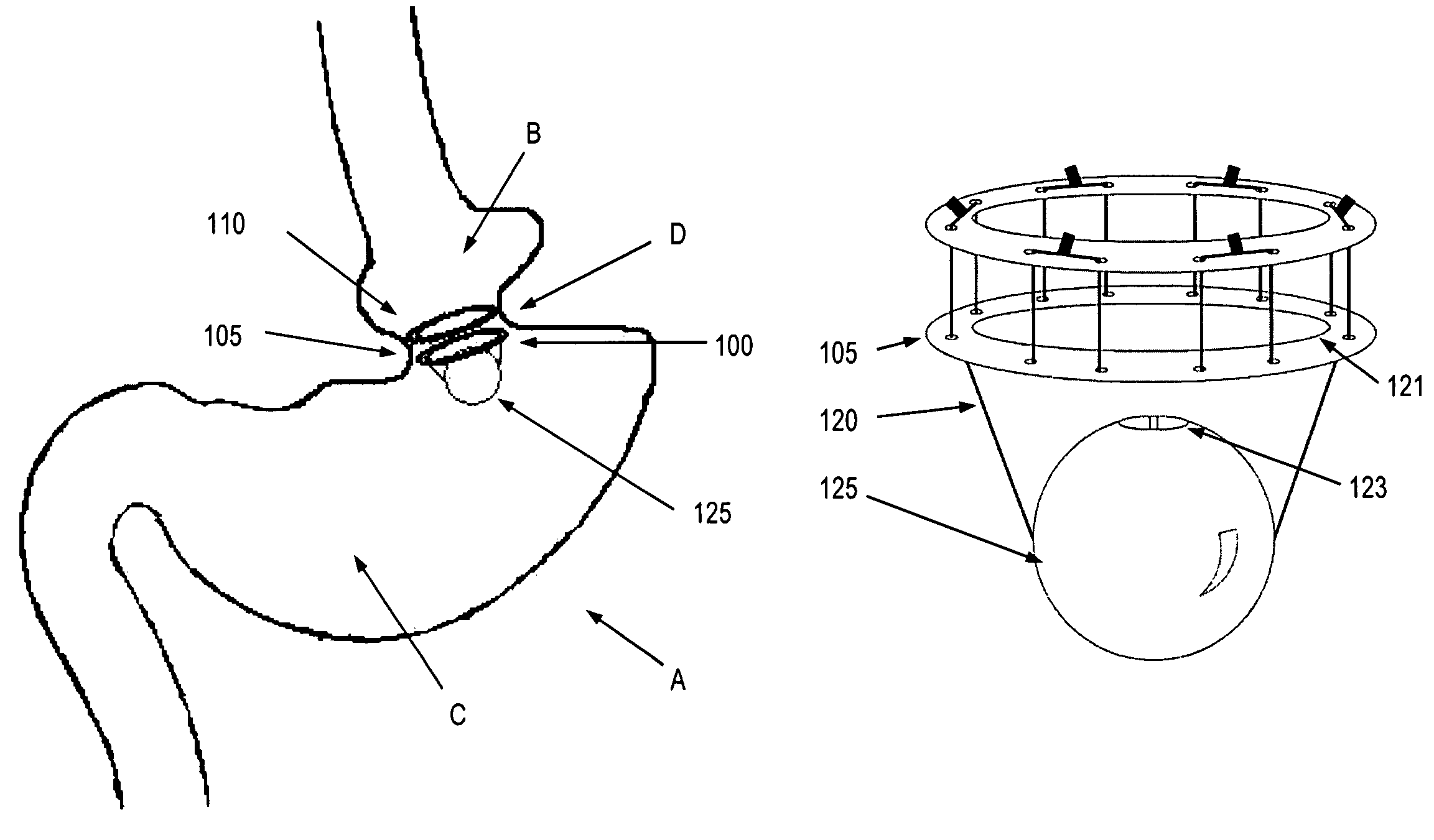
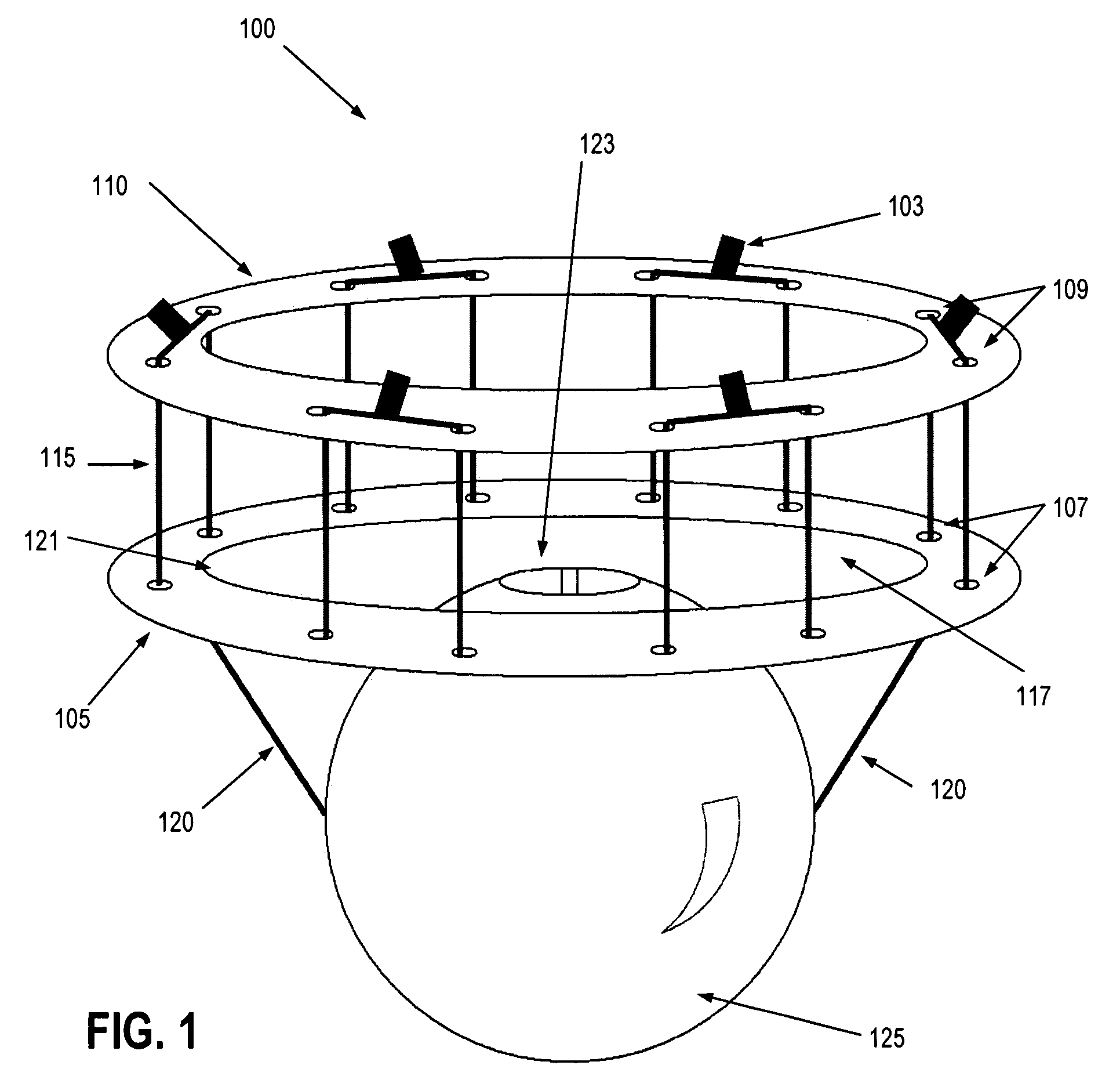
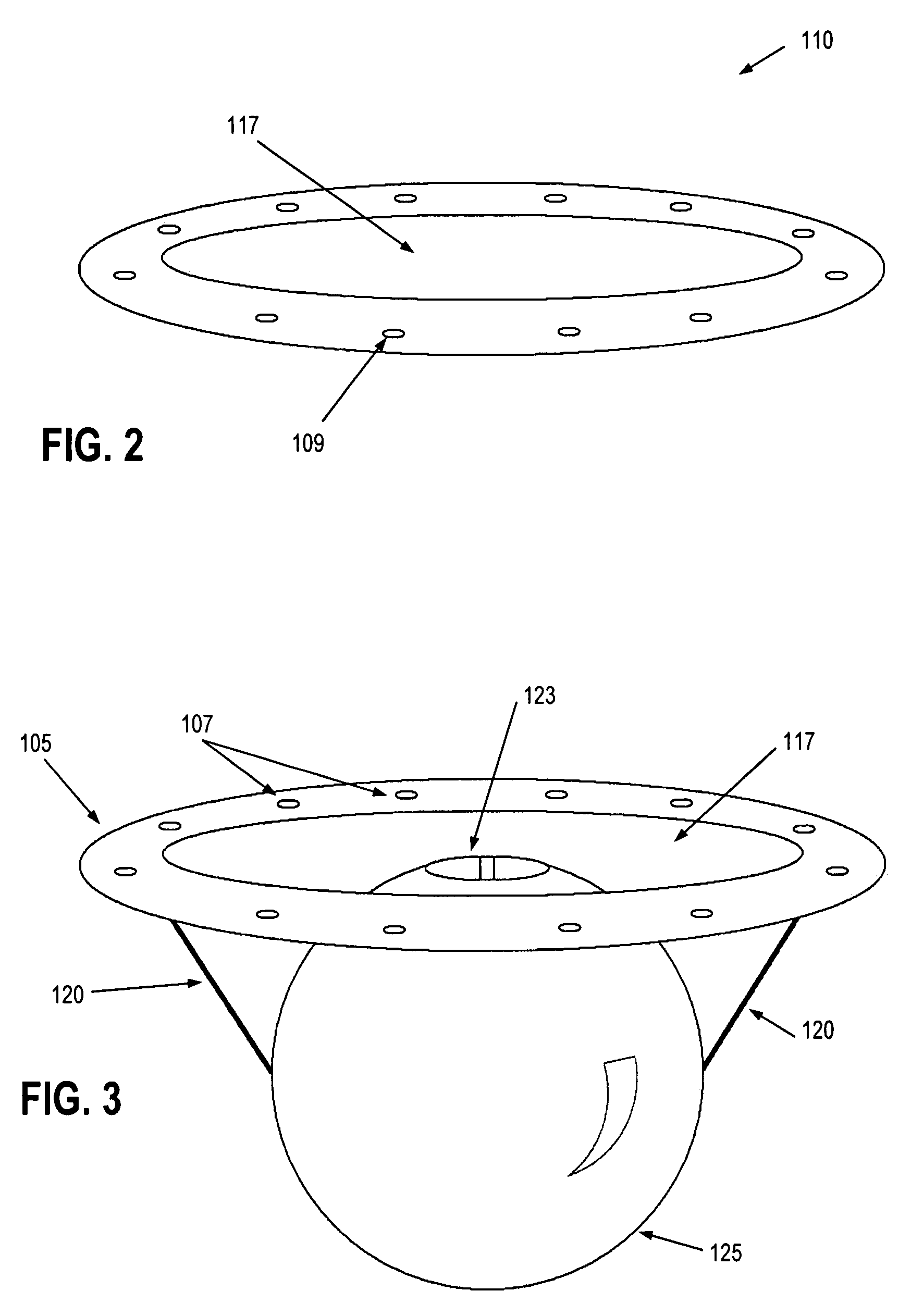
[0056]FIG. 1 illustrates an exemplary endolumenal implant 100 according to the disclosure. Endolumenal implant 100 includes a distal ring 105 that may be coupled to a proximal ring 110 by suture lines 115. Distal ring 105 and proximal ring 110 may thus be anchored to one another such that endolumenal tissue may be held therebetween in a desired configuration. Distal ring 105 and proximal ring 110 may have a plurality of first 107 and second 109 apertures, respectively, for attaching suture lines 115, or the like.

[0057]Distal ring 105 may incorporate one or more suspension lines 120 connected to distal ring 105. Suspension lines 120 may be connected at opposing sides of the circumference of the distal ring 105 or at arcuate intervals around distal ring 105 to stably suspend impeding ball 125. An impeding member, such as an impeding ball 125, may attach to distal ring 105 via suspension lines 120. Suspension lines 120 may run completely or partially through the ball, or directly attac...


PUM


Abstract

An implantable device including a supporting member, such as a ring, or series of rings, and an impeding member that is used to adjust the effective area of the created orifice after implantation. The rings may hold pleats of gastric tissue in place around their circumference to create a reinforced constriction within an organ. The rings may be attached to one another with folds or pleats of tissue held between them. If the organ is a stomach, the constriction is positioned such that a chamber of a predetermined volume is created proximal to the constriction, leaving a narrow opening or stoma to the remainder of the stomach's volume distal to the constriction. At least one of the rings is adapted to have an impeding member that may be endoscopically adjusted in order to alter the size of the effective orifice area of the opening or outlet. The occluding member may be a ball suspended by a suspension line connected to opposing sides of the supporting member.

Description

[0001]This application claims priority to Provisional Patent Application 60 / 833,262 filed on Jul. 26, 2006, and 60 / 848,644 filed on Oct. 3, 2006, which are hereby incorporated by reference for all purpose as if fully disclosed herein.BACKGROUND OF THE INVENTION[0002]1. Field of the Invention[0003]The present invention generally relates to an endolumenal surgical device and procedure for the treatment and control of obesity. More particularly, the present invention relates to a gastric ring and suspended, impeding member for treatment and control of obesity.[0004]2. Discussion of the Related Art[0005]Various related art of surgical bariatric methods and devices have been disclosed to treat morbid obesity and to control weight gain. Some of those methods include gastric bypass and small bowel bypass surgery. Stapling of portions of the stomach has also been utilized, which includes both vertical and horizontal stapling and other variations that are intended to reduce the size of the s...

Claims


Application Information

Patent Timeline
Patent Type & Authority Patents(United States)
IPC IPC(8): A61B17/08A61F2/00
CPCA61B17/0469A61F5/0079A61B17/0482A61B17/00234A61B2017/0472A61B2017/06057
Inventor BJERKEN, DAVID
Owner BERNARD MEDICAL
Learn More