
Method and system for powering an electronic device

a technology for electronic devices and power supply, applied in the direction of diagnostic recording/measuring, applications, catheters, etc., can solve the problems of limited life of batteries and periodic replacemen

Active Publication Date: 2009-11-17
ABBOTT DIABETES CARE INC
View PDF1477 Cites 71 Cited by
  • Summary
  • Abstract
  • Description
  • Claims
  • Application Information

AI Technical Summary

Benefits of technology

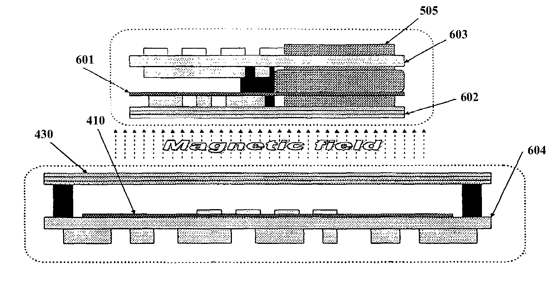
The present invention provides a way to power an analyte monitoring system using an inductive rechargeable power supply. This involves using a high frequency magnetic field to generate power for the system's battery. The technical effect is that this method and apparatus offer a reliable and efficient way to power the system, ensuring accurate and reliable data monitoring and management.

Problems solved by technology

Generally, batteries have a limited life span and require periodic replacement.

Method used


Image

  • Method and system for powering an electronic device
  • Method and system for powering an electronic device
  • Method and system for powering an electronic device

Examples


Embodiment Construction

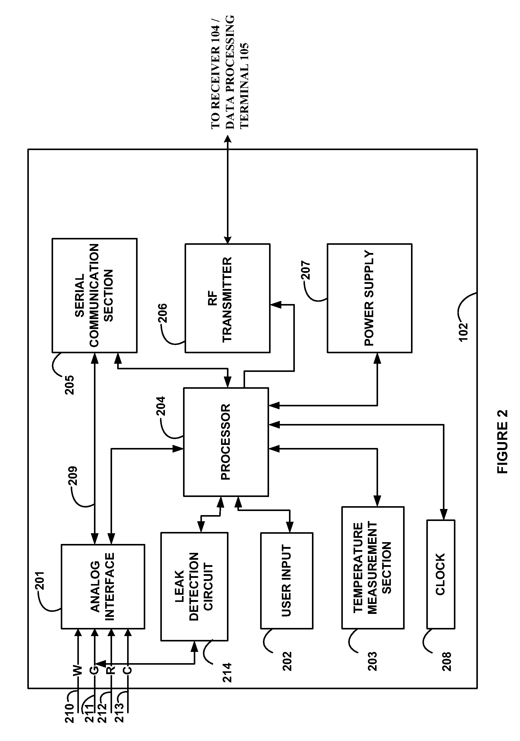
[0012]As described in accordance with the various embodiments of the present invention below, there are provided methods and system for inductively recharging a power source such as a rechargeable battery in an electronic device such as a data transmitter unit used in data monitoring and management systems such as, for example, in glucose monitoring and management systems.

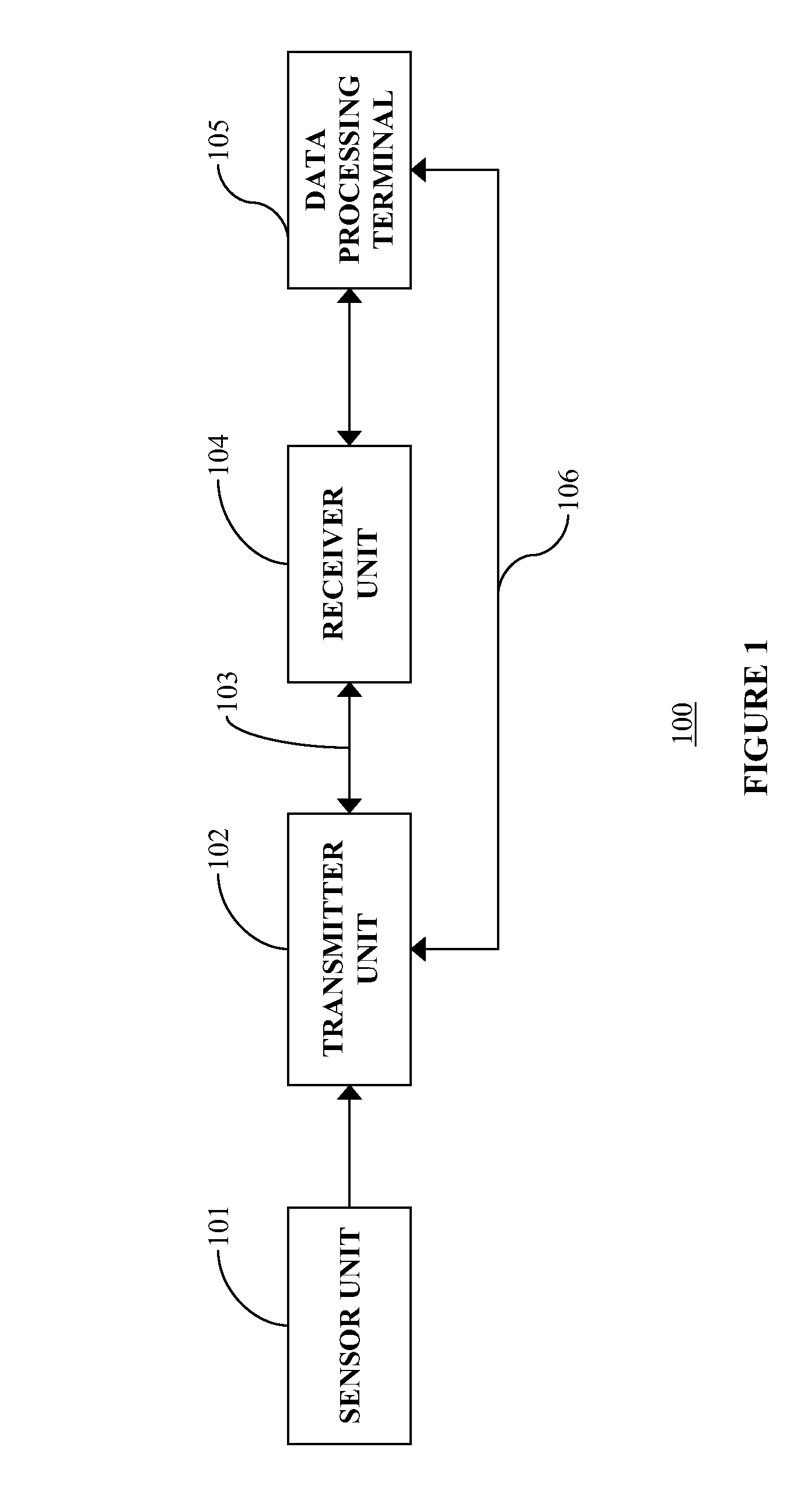
[0013]FIG. 1 illustrates a data monitoring and management system such as, for example, an analyte (e.g., glucose) monitoring system 100 in accordance with embodiments of the present invention. The subject invention is further described primarily with respect to a glucose monitoring system for convenience and such description is in no way intended to limit the scope of the invention. It is to be understood that the analyte monitoring system may be configured to monitor a variety of analytes, e.g., lactate, ketones, and the like.

[0014]Indeed, analytes that may be monitored include, for example, acetyl choline, amylas...


PUM


Abstract

Methods and apparatus for providing a power supply to a device, including an inductive rechargeable power supply for a data monitoring and management system in which a high frequency magnetic field is generated to provide power supply to a rechargeable rower source such as a battery of a transmitter unit in the data monitoring and management system are provided.

Description

BACKGROUND[0001]Analyte, e.g., glucose monitoring systems including continuous and discrete monitoring systems generally include a battery powered and microprocessor controlled system which is configured to detect signals proportional to the corresponding measured glucose levels using an electrometer, and RF signals to transmit the collected data. One aspect of certain glucose monitoring systems include a transcutaneous or subcutaneous analyte sensor configuration which is, for example, partially mounted on the skin of a subject whose glucose level is to be monitored. The sensor may use a two or three-electrode (work, reference and counter electrodes) configuration driven by a controlled potential (potentiostat) analog circuit connected through a contact system.[0002]The analyte sensor may be configured so that at least a portion thereof is placed under the skin of the patient so as to detect the analyte levels of the patient, and another portion of segment of the analyte sensor tha...

Claims


Application Information

Patent Timeline
Patent Type & Authority Patents(United States)
IPC IPC(8): A61B5/05A61B5/00
CPCA61B5/14532H02J7/00A61B5/14865A61B2560/0219A61B5/076A61B5/1451A61B5/14546H02J50/12A61B5/14503
Inventor HE, LEI
Owner ABBOTT DIABETES CARE INC
Learn More