Bullet identification and tracking device

a tracking device and bullet technology, applied in the field of bullets, can solve the problems of deteriorating barrels, debris can build up in additional grooves in barrels, and debris can accumulate in barrels, and achieve the effect of quickly recovering the wounded

Active Publication Date: 2009-11-24
CUGLIARI GREGORY ANTHONY
View PDF33 Cites 6 Cited by
  • Summary
  • Abstract
  • Description
  • Claims
  • Application Information

AI Technical Summary

Benefits of technology

[0025]This invention will minimize the number of firearm crimes because the criminals will know there is an excellent chance they will be caught. It will also put more hardened criminals in jail. This is because if the hardened criminal commits the crime without concerns of the ramification, there is a higher propensity for these criminals to be caught.
[0028]If this is used in police bullets, the police officer will be able to quickly find a wounded criminal that has fled the crime scene.
[0029]If this is used for hunting, the hunter will be able to recover the wounded game quickly, even if the game runs off several hundred yards and has left no tracking signs (i.e., blood trail, and other normal tracking signs).

Problems solved by technology

The markings on the inside wall of the barrel can result in the barrel deteriorating.
Also, debris can build up in the barrel.
Also, debris can build up in the additional grooves in the barrel.
In addition, many times the bullet passes through the object and the bullet is never recovered, rendering the system ineffective.
If the bullet is significantly damaged during penetration, the markings may not be legible, rendering the system ineffective.

Method used


Image

  • Bullet identification and tracking device
  • Bullet identification and tracking device
  • Bullet identification and tracking device

Examples


Embodiment Construction

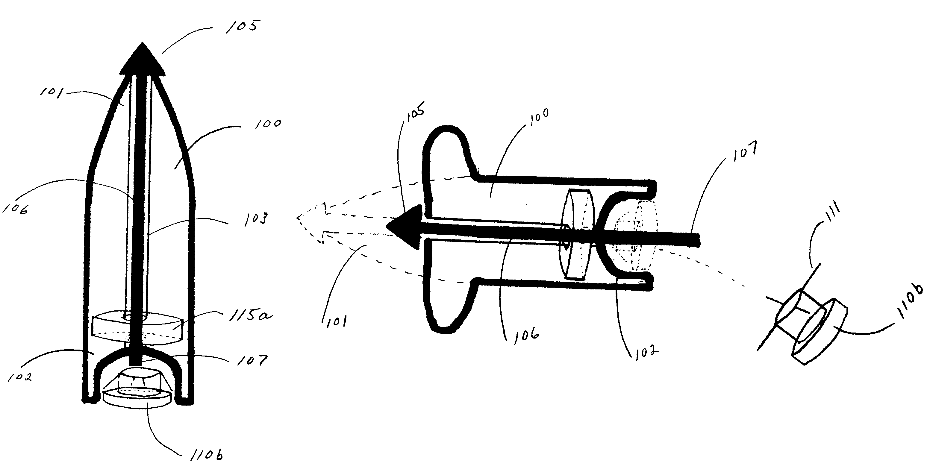
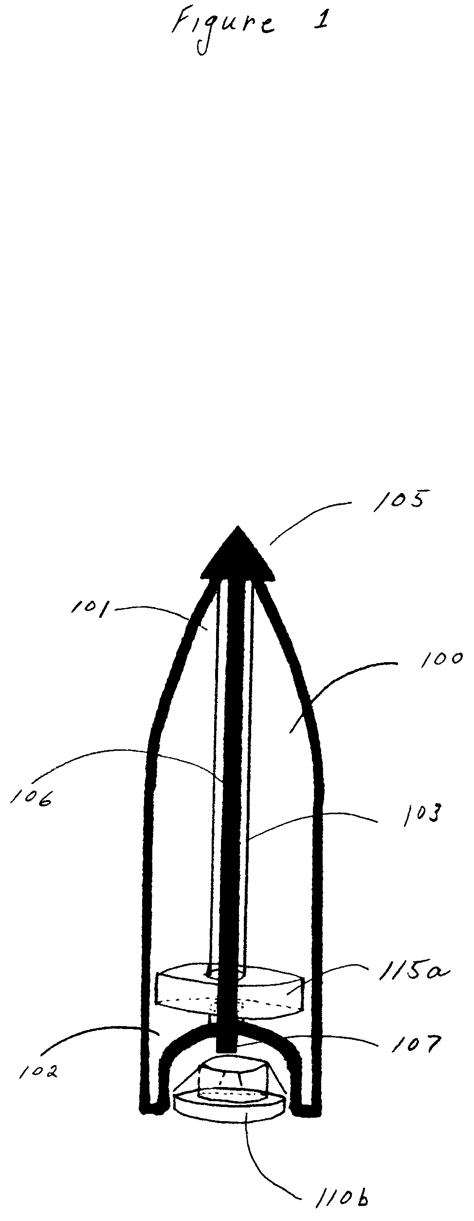
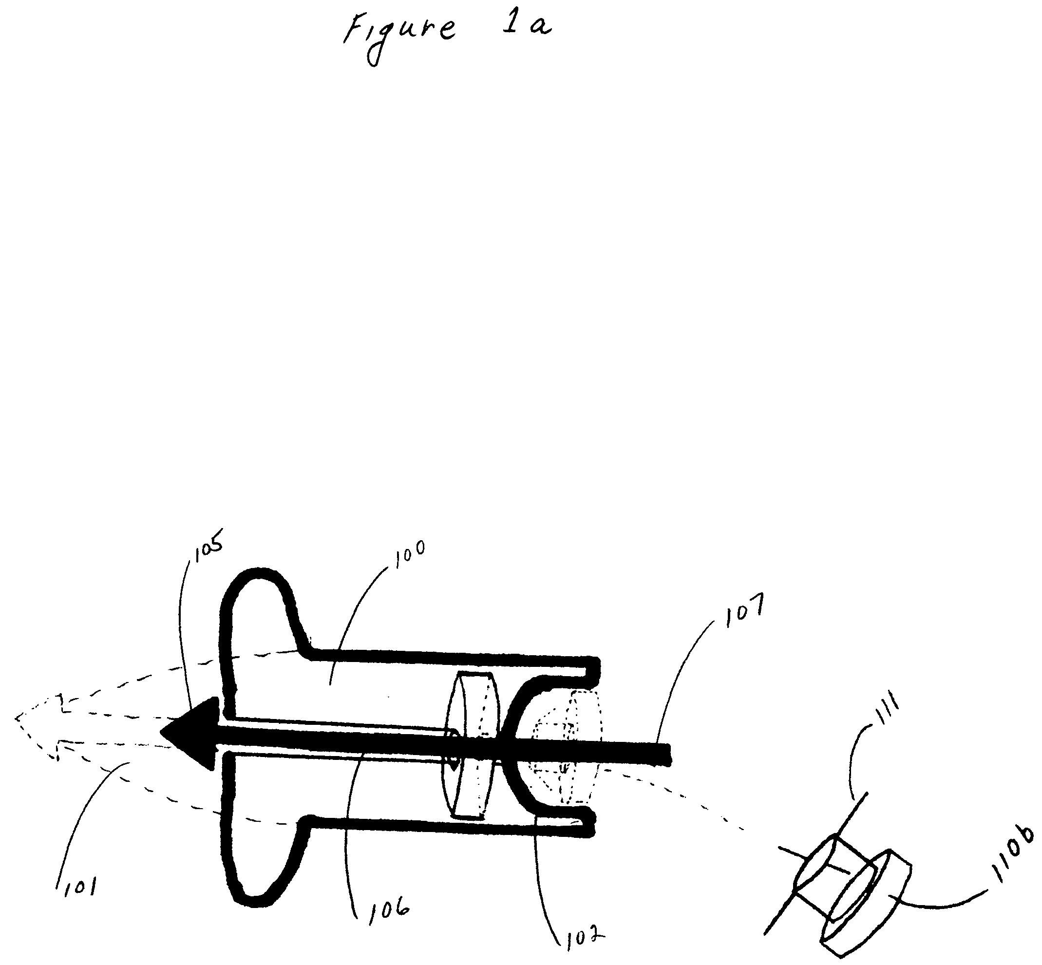
[0068]Referring now to the drawings, wherein like reference numerals designate identical or corresponding parts throughout the several views, FIG. 1 shows a bullet (100) with two identification devices attached. The bullet (100) has an aperture (103) which runs through the center of the bullet from the bullet tip (101) at the proximal end of the bullet to the bullet tail end (102) at the distal end of the bullet. The aperture (103) is of sufficient width to house the trigger shaft (106). The trigger tip (105) is connected to the trigger shaft (106). The trigger shaft (106) transverses the center of the bullet (100) from the bullet tip (101) to the bullet tail end (102). A barbed detaching device (110b) is pressure fitted into a hollow bullet tail end (102). Stated another way, the device is detachably affixed in an aperture at the distal end of the bullet. Another device, an embedded device (115a) is permanently embedded inside the metal of the bullet (100). Upon penetration of the ...


PUM


Abstract

An identification and tracking device (110b) for use in combination with a firearm bullet (100) comprising a means for detaching the device (110b) from the bullet (100) during penetration of the target. In this manner, the tracking device (110b) and / or identification device (110b) will be attached to an object when the bullet (100) penetrates the object.

Description

BACKGROUND[0001]1. Field of Invention[0002]The present invention relates generally to bullets which are capable of being discharged through the muzzle of a firearm. The bullets are generally used for hunting, but can also be used for other reasons including criminal activities. More particularly, the present invention relates to tracking an object hit by the bullet and identifying the individual bullet which was discharged from the firearm.[0003]2. Description of Prior Art[0004]Bullet identification systems have generally consisted of markings on the inside wall of a gun barrel. In this manner, the inventions can place markings on the bullet. If the markings on the bullet are not materially damaged, they can be used to identify the gun that was used to discharge the bullet. The markings on the inside wall of the barrel can result in the barrel deteriorating. Also, debris can build up in the barrel. Also, debris can build up in the additional grooves in the barrel. In addition, many ...

Claims


Application Information

Patent Timeline
Patent Type & Authority Patents(United States)
IPC IPC(8): F41A9/53
CPCF42B12/36F42B12/365F42B35/00F42B12/625F42B12/40
Inventor CUGLIARI, GREGORY ANTHONY
Owner CUGLIARI GREGORY ANTHONY
Why Eureka
Try Eureka