System for pressurized delivery of fluids

a technology of fluid delivery and pressurized gas, which is applied in the direction of transportation and packaging, combustion types, lighting and heating apparatus, etc., can solve the problems of affecting the delivery characteristics of the contents of the package, and affecting the delivery of fluids

Inactive Publication Date: 2009-11-24
PROCTER & GAMBLE CO
View PDF6 Cites 30 Cited by
  • Summary
  • Abstract
  • Description
  • Claims
  • Application Information

AI Technical Summary

Problems solved by technology

Such pressure decay may transmogrify the delivery characteristics of the contents of the package.
However, the pressure decay of a compressed gas system is typically more noticeable throughout the life of the system.
However, over time, the pressure decay of the propellant causes each of these delivery characteristics to change.
However, as particle size increases during the pressure decay, the user is not able to compensate.
An increase in particle size may be undesirable.
For example, as particle size of a hairspray increases, the polymer may become too sticky.
However, some ratios less than 2:1 have been found to work well while some ratios greater than 2:1 have been found unsuitable.

Method used


Image

  • System for pressurized delivery of fluids
  • System for pressurized delivery of fluids
  • System for pressurized delivery of fluids

Examples


Embodiment Construction

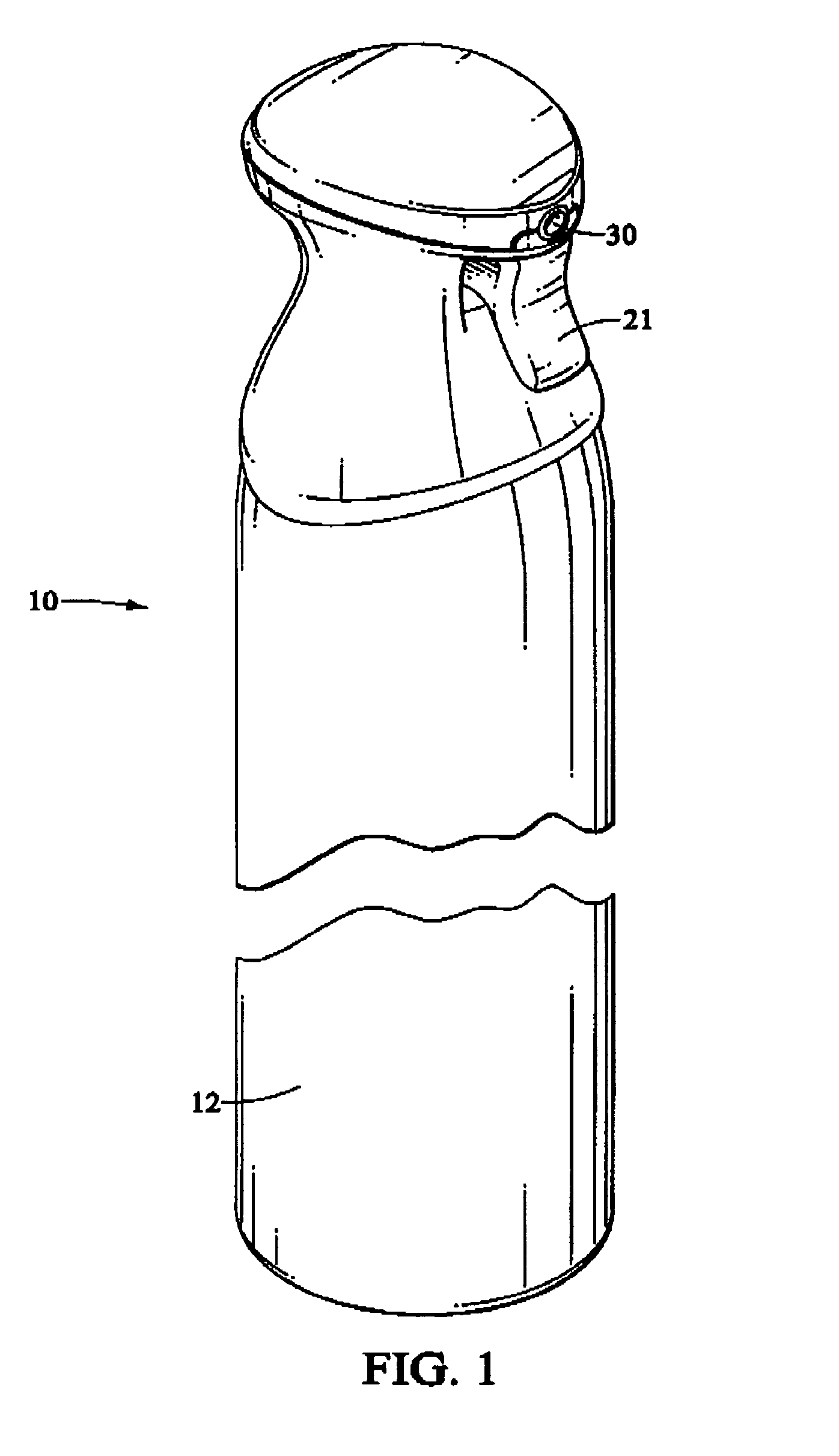
[0015]Referring to FIG. 1, a typical dispensing system comprises a package 10. Contents to be dispensed and a propellant are contained in the package 10. The contents and propellant may be intermixed at an interface or may be kept separate, using an inflatable bag, as are known in the art.

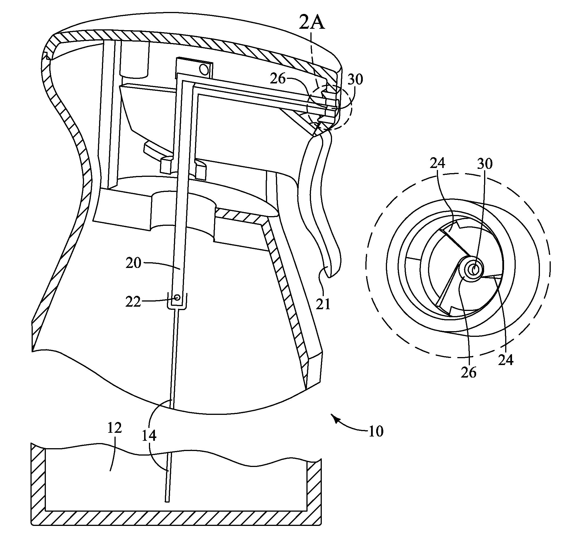
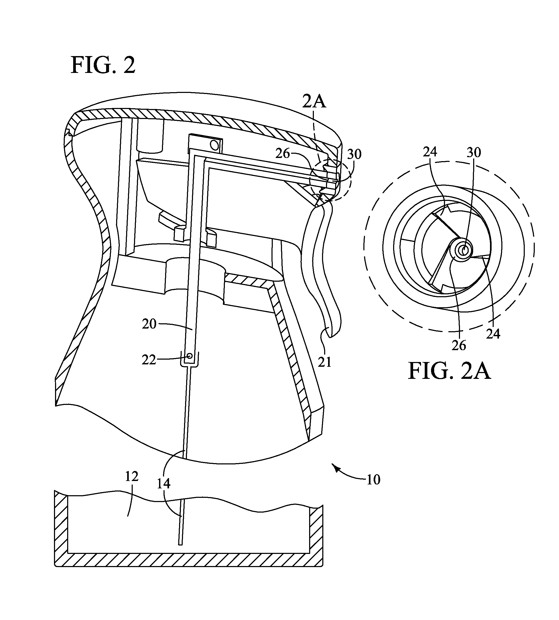
[0016]Referring to FIG. 2, the contents are dispensed in a sequential flow path. While many executions of a flow path from storage in the package 10 to spray to the atmosphere / ambient are known, one illustrative embodiment will be described herein. However, one of skill will recognize the invention is not so limited.

[0017]The contents to be dispensed are contained in a reservoir 12 and may enter the flow path through a dip tube 14. The dip tube 14 may be of constant or variable cross section. If the dip tube 14 has a variable cross section, the portion of the dip tube 14 having the greatest flow restriction (smallest flow area / hydraulic radius) is considered. If the dip tube 14 has a constant cross...


PUM


Abstract

A pressurized spray system. The spray system has a flow path through which contents must pass to be dispensed from the system to the atmosphere. By maintaining the proper proportions of restrictions in the flow path to the spray nozzle exit orifice, a relatively constant mean particle size distribution may be obtained throughout the life of the spray system as the pressure decays.

Description

FIELD OF THE INVENTION[0001]The present invention relates to systems which deliver liquids and more particularly for systems which deliver liquids under pressure.BACKGROUND OF THE INVENTION[0002]Spray systems, particularly pressurized spray systems, are well-known in the art. Such spray systems often utilize a metal can, plastic container or other package charged with a propellant. The propellant pressurizes the contents of the spray system to a pressure greater than atmospheric. Upon release of the propellant pressurizing the contents of the package, the pressure differential causes discharge of the contents to the atmosphere or ambient surroundings.[0003]Typical propellants include compressed gasses, such as nitrogen, or hydrocarbon such as butane. One characteristic common to both compressed gas and hydrocarbon propellants is that the pressure decays with repeated uses, as illustrated. Such pressure decay may transmogrify the delivery characteristics of the contents of the packag...

Claims


Application Information

Patent Timeline
Patent Type & Authority Patents(United States)
IPC IPC(8): B05B1/34B65D83/28
CPCB65D83/753B65D83/206B05B1/3436B05B7/10B65D83/62
Inventor SMITH, SCOTT EDWARDCANNON, WILLIAM MICHAELWINTMOLDERS, WIM
Owner PROCTER & GAMBLE CO
Why Eureka
Try Eureka