Magnetic head test method and magnetic head tester

a magnetic head and test method technology, applied in the field of magnetic head test methods and magnetic head testers, can solve the problems of noise in the electrical measurement of the magnetic head, one of the two magnetic heads not always completed, and the accuracy of the magnetic head is not always guaranteed, so as to improve the efficiency of the magnetic head test

Inactive Publication Date: 2009-11-24
HITACHI HIGH-TECH CORP
View PDF6 Cites 11 Cited by
  • Summary
  • Abstract
  • Description
  • Claims
  • Application Information

AI Technical Summary

Benefits of technology

[0014]An object of this invention is to provide a test method or a magnetic head tester with which the exchange operation for unloading a tested magnetic head assembly from a head clamp table and loading a new magnetic head assembly to be tested on the head clamp table can be automated and through-put of the magnetic head test processing can be improved.
[0023]In this invention, the magnetic head assembly can be easily mounted on the clamp table by positioning the magnetic head assembly by fitting the mounting hole thereof in the boss pin or the receiving hole in the tray, the pin or the hole in the mounting table and the positioning pin in the head clamp table, respectively, positioning the suction portion on the mounting hole of the mounting base in the boss pin or the receiving hole in the tray, the pin or the hole in the mounting table and the positioning pin in the head clamp table, respectively, sucking the mounting base of the magnetic head assembly and transferring the magnetic head assembly from the tray to the clamp table by the handling robot without requiring high positioning accuracy. By temporarily positioning the magnetic head assembly on the clamp table which is provided in the transporting way such that the magnetic head assembly is put in the mounting direction of the clamp table, the magnetic head assembly can be reliably mounted on the clamp table by the handling robot such that the magnetic head assembly can be clamped selectively.
[0026]Therefore, it is possible to automatically set the magnetic head assembly without considerable design change of the clamp mechanism of the clamp table and the clamping operation. Further, it can easily derive the magnetic head assembly from the clamp table automatically by positioning the sucking portion in the clamp table and sucking the magnetic head assembly on the clamp table whose clamping is released.
[0027]As a result, it is possible to automate the exchanging operation including the unloading of the tested magnetic head assembly and the setting of a new non-tested magnetic head assembly on the clamp table, so that through-put of the magnetic head test processing can be improved.
[0029]Since, therefore, the test processing in the first and second test decks can be executed alternately, a continuous test of magnetic head becomes possible and the efficiency of the magnetic head test can be improved.

Problems solved by technology

The size and configuration of the current magnetic head assembly is very small as mentioned previously and, when a magnetic head floats from a magnetic disk by a small gap of several to 10 nm, even when one of the magnetic heads is exchanged by the other magnetic head by moving the one magnetic head from the magnetic disk to a vicinity of its periphery during the test of the other magnetic head, the exchange must be performed carefully and so a noise problem occurs in the electrical measurement of the magnetic head under the test.
However, the use of one of two magnetic heads is not always completed during a test of the other magnetic head and cross-talk noise may occur in the simultaneous tests of the magnetic heads.
Further, when a tested magnetic head assembly on the spindle is completed is exchanged by a magnetic head assembly to be tested manually, the improvement of the through-put of the testing is limited.
Therefore, it is very difficult practically to freely design and change them.

Method used


Image

  • Magnetic head test method and magnetic head tester
  • Magnetic head test method and magnetic head tester
  • Magnetic head test method and magnetic head tester

Examples


Embodiment Construction

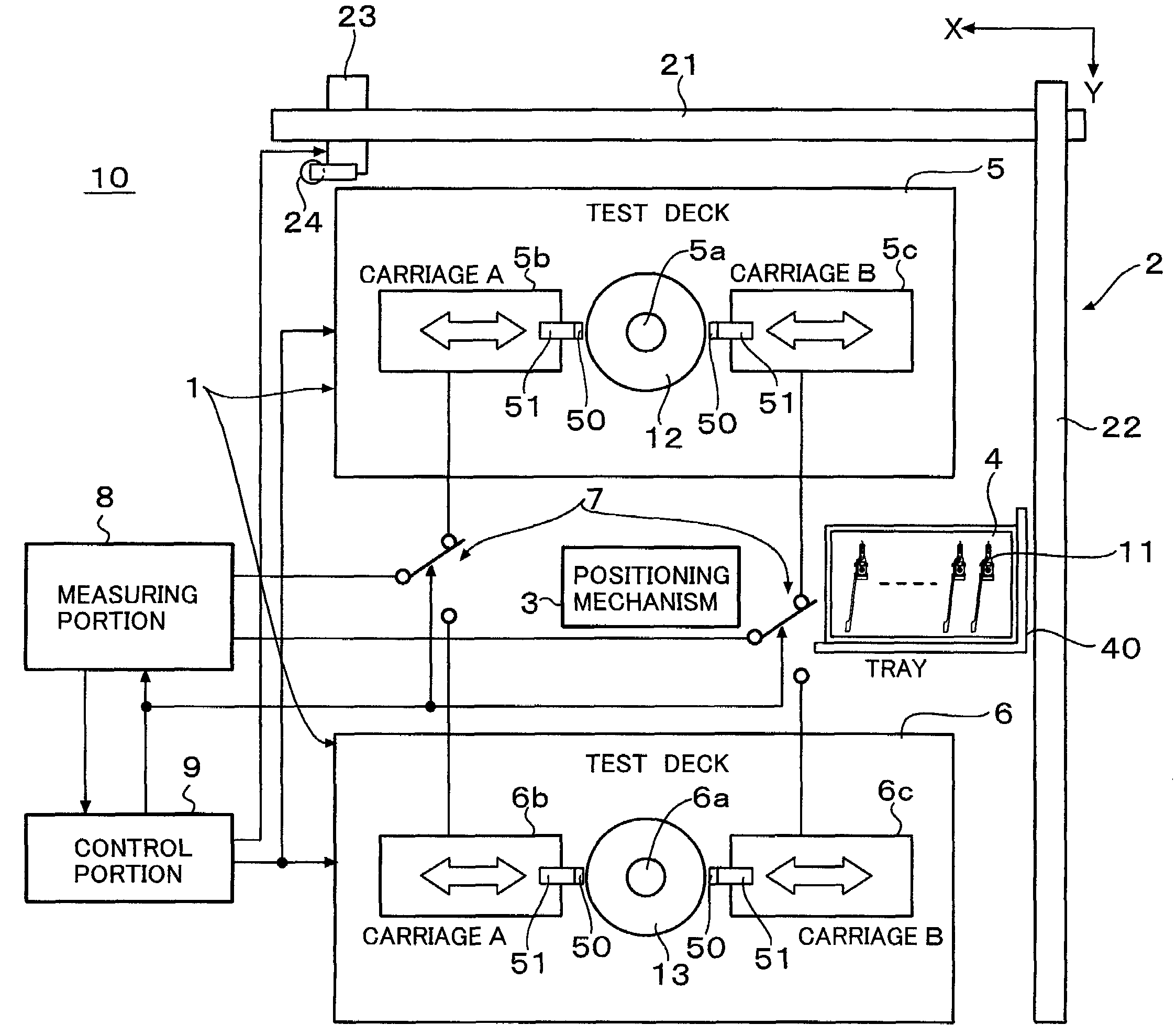
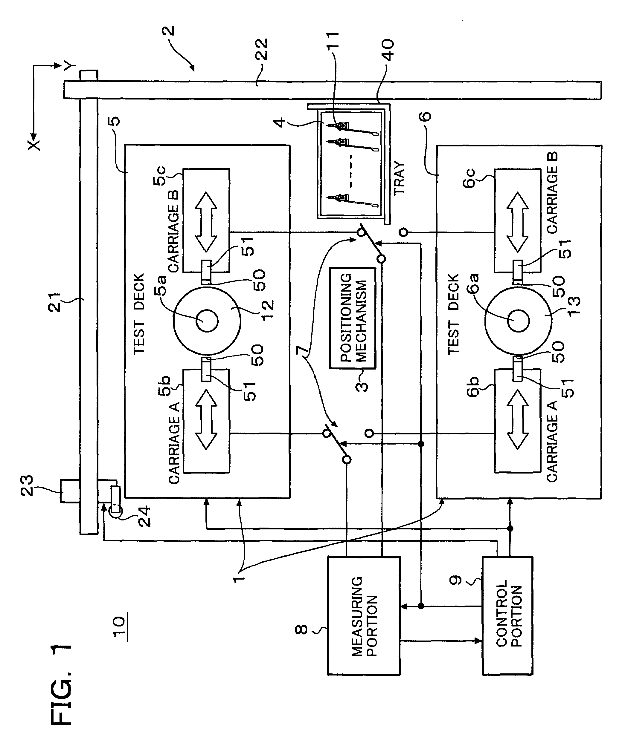
[0036]In FIG. 1, a reference numeral 10 depicts a magnetic head tester which includes a plurality of test stages 1, a handling robot 2, a positioning mechanism 3 and a tray 4 for arranging and storing magnetic head assemblies.

[0037]Each of the test stages 1 includes a test deck 5 (6), switching circuits 7 and a measuring portion 8 connected to the test decks through the switching circuit 7. A control portion 9 for controlling the test decks and the handling robot 2, etc., is provided. The test deck 5 includes a spindle 5a and a head carriage 5b (carriage A) and a head carriage 5c (carriage B) and the test deck 6 includes a spindle 6a and a head carriage 6b (carriage A) and a head carriage 6c (carriage B). Magnetic disks 12 and 13 are mounted on the spindles 5a and 6a and rotated, respectively.

[0038]Head arms or carriage arms 51 for supporting magnetic head assemblies are provided in the head carriages 5b (5c) and 6b (6c), respectively, and clamp tables 50 (refer to FIG. 5(a)) are fi...


PUM


Abstract

A magnetic head assembly having a mounting base in which a mounting hole having a protruded peripheral edge is formed is easily mounted on a head clamp table positioning the magnetic head assembly by fitting the mounting hole on a boss pin or a receiving hole of a tray, with a pin or a hole on a mounting table and with a positioning pin on a head clamp table and positioning a suction collet with using a boss pin or a receiving hole of a tray as references, and sucking the mounting base of the magnetic head assembly by a handling robot without requiring high positioning accuracy.

Description

TECHNICAL FIELD[0001]This invention relates to a magnetic head test method and a magnetic head tester and, in particular, this invention relates to a magnetic head test method and a magnetic head tester, in which a magnetic head assembly (including a magnetic head and a suspension spring) is set on a head clamp table of a magnetic head tester, the magnetic head of the magnetic head assembly is tested, the magnetic head assembly is unloaded from the head clamp table after tested and a new head assembly to be tested is set on the head clamp table, so that an exchange work of magnetic head assembly can be automated and through-put of a magnetic head testing processing or the tester can be improved.BACKGROUND ART[0002]The recording density of a magnetic disk has been increased recently and the recording density of the current hard disk drive (HDD) is in the order of several hundreds giga-bits. With such increased recording density of the magnetic disk, a floating distance of a magnetic ...

Claims


Application Information

Patent Timeline
Patent Type & Authority Patents(United States)
IPC IPC(8): G01R33/12G01R33/00
CPCG11B27/36G11B2220/2516
Inventor SUGIYAMA, TOSHINORIMOCHIZUKI, HIDEKIHONMA, SHINJITOKUMURA, YOSHINORI
Owner HITACHI HIGH-TECH CORP
Why Eureka
Try Eureka