System for and method of reducing change caused by motor vibrations in ellipsometers, polarimeters or the like

a technology of ellipsometers and polarimeters, applied in the field of system and method of reducing the change caused by motor vibrations in ellipsometers, polarimeters or the like, can solve the problems of vibration caused, the measurement results will not accurately represent the location it is intended, and the motor can affect the location

Active Publication Date: 2009-11-24
J A WOOLLAM CO
View PDF15 Cites 2 Cited by
  • Summary
  • Abstract
  • Description
  • Claims
  • Application Information

AI Technical Summary

Benefits of technology

[0026]Another recitation of a present invention system for maintaining the locus of a beam of electromagnetic radiation, provides that said system comprise a source means for providing a beam of electromagnetic radiation and a motor driven component, said system further comprising a means for damping vibrations caused by the operation of said motor such that vibrations do not cause displacement of the beam locus. Said system is characterized by further comprising a polarizer, an analyzer, a detector and mounting arms, with said source means and polarizer being mounted to one said mounting arm and said analyzer and detector being mounted to another of said mounting arms. In use said motor is applied to drive a beam polarization state changing element, (eg. polarizer, analyzer, compensator). The system is characterized by the presence of a means for damping vibrations, the purpose thereof being to damp vibrations produced by the operation of said motor so that change in the locus of the beam is reduced. This has the effect of maintaining the location on a sample at which said electromagnetic beam impinges thereupon.
[0030]Said system can further comprise means for damping vibrations caused by the operation of said motor in the form of a securing means which secures said motor to said stationary support, said stationary support being more massive than necessary to support the motor.Said system can further comprise means for damping vibrations caused by the operation of said motor comprising a securing means which secures said motor to a stationary support, said stationary support having an additional stationary support secured thereto to increase vibration damping capacity.
[0032]a) providing a system comprising a motor driven component and a means for providing a beam of electromagnetic radiation to a small specific location on a sample, said system further comprising a means for damping vibrations caused by the operation of said motor such that vibrations do not cause displacement of the beam locus;

Problems solved by technology

A problem which develops in very precise measurements is that vibrations caused by operation of said motor can affect the location on said sample where the beam impinges by altering the beam locus.
In said very precise work the specific location on a sample where the focused beam impinges can affect how the polarization state of the beam is changed by interaction with said sample, and if the impingement position changes even a very small amount, the measurement results will not accurately represent the location it is intended to investigate.
Further, undamped vibrations can have an effect on other components in a system.

Method used


Image

  • System for and method of reducing change caused by motor vibrations in ellipsometers, polarimeters or the like
  • System for and method of reducing change caused by motor vibrations in ellipsometers, polarimeters or the like
  • System for and method of reducing change caused by motor vibrations in ellipsometers, polarimeters or the like

Examples


Embodiment Construction

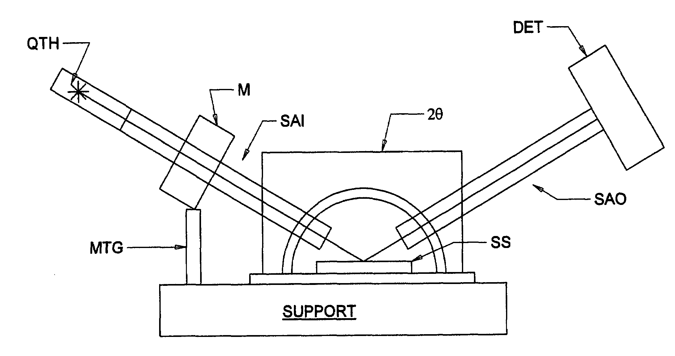
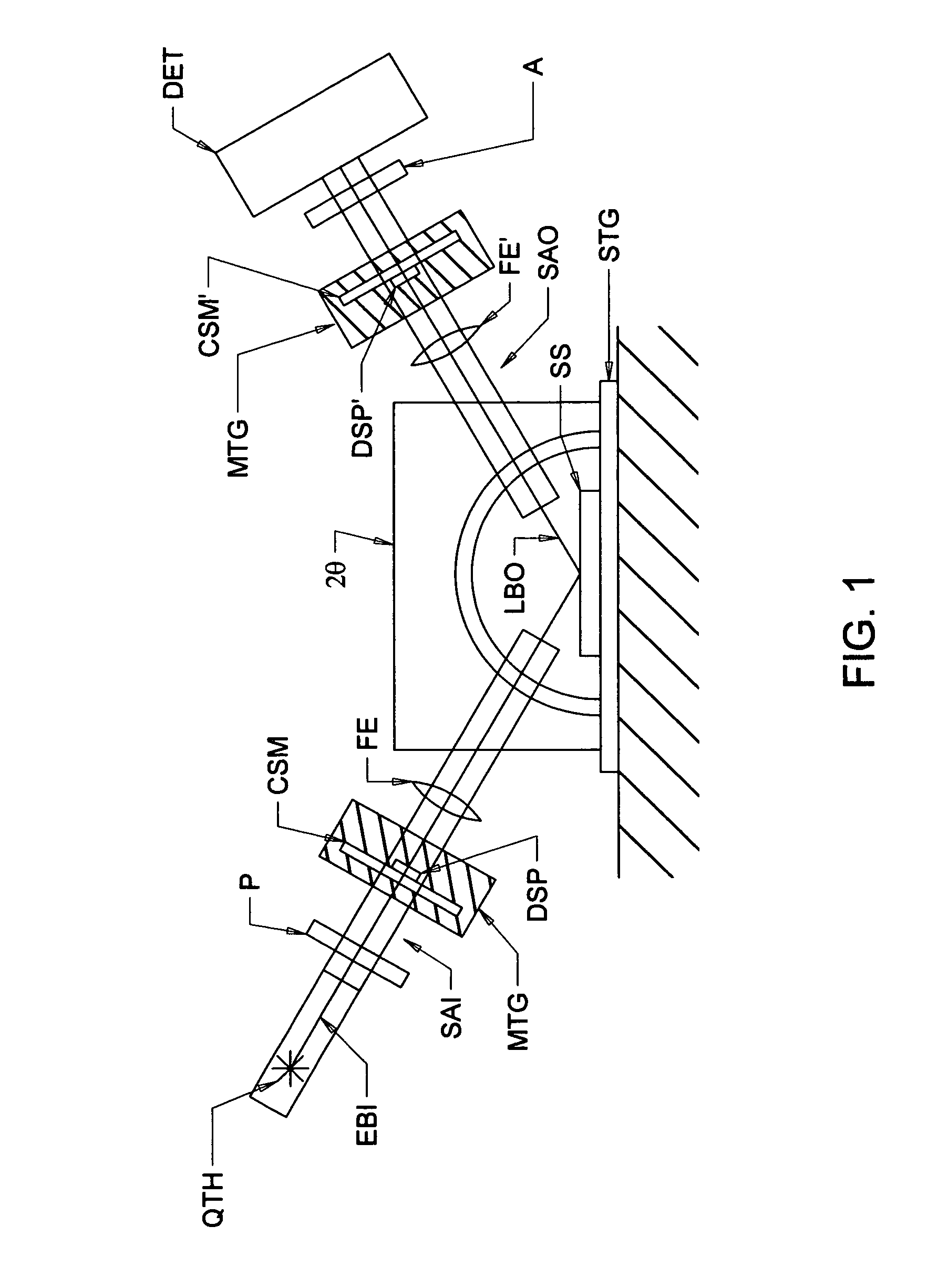
[0055]FIG. 1 demonstrates that an ellipsometer system can comprise a Source of a beam of electromagnetic radiation (QTH), a Polarizer (P), a Continuously Rotating or Stepped Motor (DSM) in combination with a Compensator (CSM), a Focusing Means (FE), a Sample (SS) on a Stage (STG), a Collimating Focusing Means (FE′), optionally a second Stepped Motor (DSP′) in combination with a Compensator (CSM′), an Analyzer (A) and a Detector (DET). Physical systems typically mount all said elements to arms Arms (SAI) (SAO) which project at some oblique angles as shown in FIG. 1. Such mounting allows for vibrations caused by operation of a Motor (DSM) to propagate to the Focusing Elements (FE) and / or (FE′), and motion thereof leads to changed location of the electromagnetic beam on said Sample (S).

[0056]The present invention can be demonstrated by the provision of at least one additional mounting element, (see the elements identified as (MTG) and (MTG′), in FIG. 1), which damp vibrations caused by...


PUM


Abstract

A system and method which reduces change in locus of a beam of electromagnetic radiation which otherwise result from vibrations caused by operation of a motor which controls the rotation of an element which affects the beam.

Description

[0001]This Application Claims Benefit of Provisional Application 60 / 811,391 Filed Jun. 7, 2006.TECHNICAL FIELD[0002]The present invention relates to systems which direct beams of electromagnetic radiation onto samples such as ellipsometer, polarimeter or the like systems, which contain at least one motor driven rotating, or rotatable element. More particularly the present invention is a system and method which reduces change in beam locus as a result of vibrations caused by operation of said motor.BACKGROUND[0003]It is known to direct a beam of electromagnetic radiation at a sample, optionally via a focusing means, such that said beam is focused onto a very small spot on said sample. It is further known to monitor a sequence of beam polarization states which are imposed on said beam and which are affected by interaction with said sample. Often said polarization states are mediated by application of a motor to effect continuous rotation, or stepped rotation of an element such as a po...

Claims


Application Information

Patent Timeline
Patent Type & Authority Patents(United States)
IPC IPC(8): G01J4/00
CPCG01N21/211G01J2003/062
Inventor HE, PINGLIPHARDT, MARTIN M.
Owner J A WOOLLAM CO
Why Eureka
Try Eureka