
Wireless lock system

a key system and wireless technology, applied in the field of wireless lock and key system, can solve the problems of inability to easily limit the use of keys, inability to validate keys, and user still having to carry many keys, so as to minimize the need for control panels, reduce the need for key and lock devices, and increase security

Active Publication Date: 2009-11-24
III HLDG 3
View PDF36 Cites 56 Cited by
  • Summary
  • Abstract
  • Description
  • Claims
  • Application Information

AI Technical Summary

Benefits of technology

"The present invention is a wireless lock and key system that utilizes encryption keys and control devices for lock and key devices. The system has the ability to generate tickets for temporary or limited use by other authorized persons. It also allows for the use of Bluetooth or other short range communication for wireless communication between lock devices, key devices, and control devices. The system uses digital signatures and public key cryptography to enhance security and create temporary or limited keys. The key device contains both the public key and secret key of the user, and access permissions or tickets can be created for different users and contain additional information. The system can be used in virtual lock and key systems and also in computer and file access control. The technical effects of the invention include increased security, flexibility, and ease of use for lock and key devices."

Problems solved by technology

There are four main lock types, and each has its problems:1) Mechanical locks, where the secret is the way the key is formed.The user has to carry a separate key for each lock he can access. The keys have to be dug out of handbag or pocket every time a door is opened.Distribution of keys is cumbersome and has to be done by hand.Creating keys requires special equipment.Invalidating keys is hard.The use of keys cannot easily be limited (e.g. to office hours).2) Electronic locks with (possibly wireless) keys, where the secret is an access code stored in both lock and key.While a key may have space for several codes, this is uncommon and the number of codes is limited.
Thus, the user still has to carry many keys, especially as the systems are incompatible with each other.
Thus, you would have to trust the owners of all locks that you use.Distribution of keys is cumbersome and has to be done by hand.Creating new keys usually requires special equipment, and even if a key can store several codes, access to the lock is required.
While access to the lock is not necessary if a single, known code for the lock is always used, this would also mean that all the created keys share the same code and cannot be separately controlled.

Method used


Image

  • Wireless lock system
  • Wireless lock system
  • Wireless lock system

Examples


Embodiment Construction

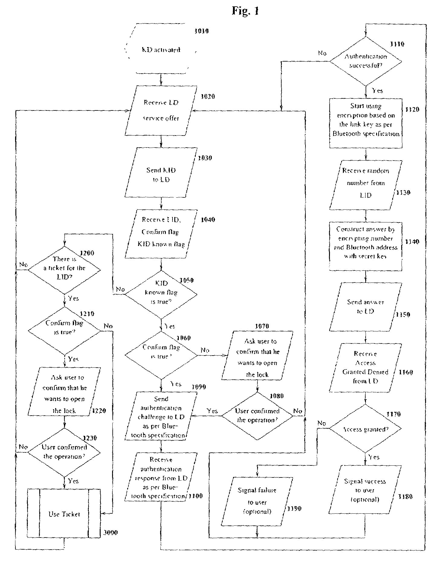
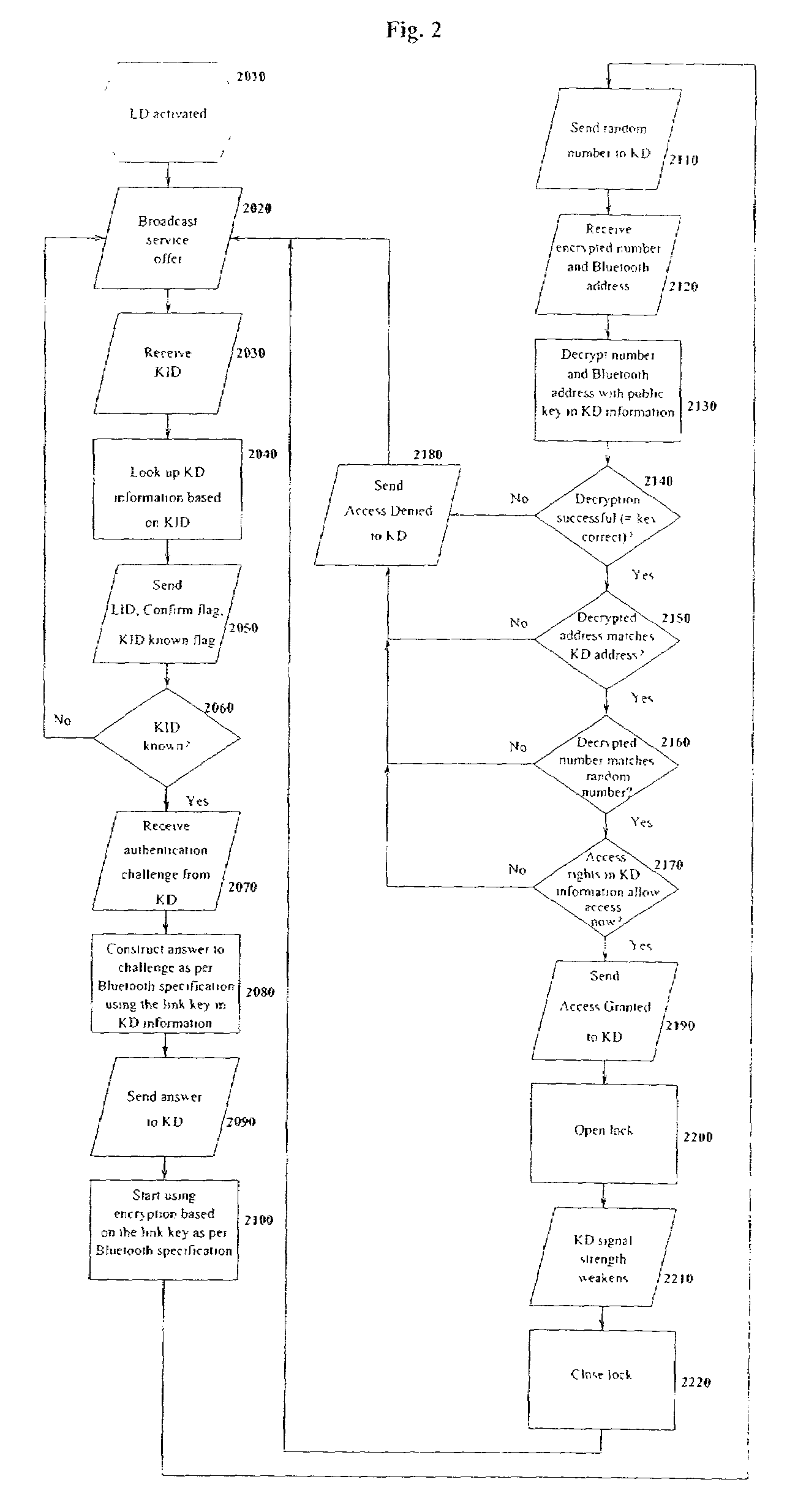
[0054]The basic environment of the embodiment of the present invention is to utilize an electronic key for wirelessly opening an electronic lock. The key is carried on a person either as part of his wireless telephone or as a separate unit which can be carried or worn on his person, such as in a belt buckle or in a piece of jewelry. When a person approaches the lock, his presence is sensed. Either the lock or the key may initiate the transaction. In a preferred embodiment the lock transmits a signal to see if a key is carried by the person. The lock sends a random data signal to the key. The key encrypts this data and sends it back to the lock. The lock decrypts the signal and, if it matches the original signal, opens the lock.

[0055]The encryption uses an encryption key pair system, with the public key being carried in the lock and the private key being carried in the key. This allows the user to use a single key for multiple locks. Thus, his public key may be stored in any number o...


PUM


Abstract

A wireless lock and key system using an encryption key pair. When a lock senses a person nearby, the random signal is generated. The key encrypts the signal and returns it to the lock. The lock decrypts the signal and compares it to the original to determine if the lock should be opened. The key may generate temporary tickets for guests to open the lock for limited times.

Description

BACKGROUND OF THE INVENTION[0001]1. Field of Invention[0002]The invention relates generally to a wireless lock and key system and more particularly to controlling and managing an electronic lock, key and control device, and to creating easily distributable temporary keys to said locks.[0003]2. Description of the Prior Art[0004]Current locks are all based on the principle of a shared secret between the lock and the key. There are four main lock types, and each has its problems:[0005]1) Mechanical locks, where the secret is the way the key is formed.[0006]The user has to carry a separate key for each lock he can access.[0007] The keys have to be dug out of handbag or pocket every time a door is opened.[0008]Distribution of keys is cumbersome and has to be done by hand.[0009]Creating keys requires special equipment.[0010]Invalidating keys is hard.[0011]The use of keys cannot easily be limited (e.g. to office hours).[0012]2) Electronic locks with (possibly wireless) keys, where the secr...

Claims


Application Information

Patent Timeline
Patent Type & Authority Patents(United States)
IPC IPC(8): G06F21/00G06F21/35G07C9/00
CPCG06F21/35G07C9/00309G07C9/00857G07C2209/04G07C2009/00412G07C2009/005G07C2009/00865G07C2009/00388
Inventor OSKARI, KOSKIMIES
Owner III HLDG 3
Learn More