Peristaltic pump

a peristaltic pump and pump body technology, applied in the direction of positive displacement liquid engine, prosthesis, medical science, etc., can solve the problems of increasing low design efficiency, and a so as to minimize the noise, reduce the problem of single stressed area in the peristaltic pump, and reduce the size of the machin

Inactive Publication Date: 2009-12-01
CHENG ZAIJUN
View PDF4 Cites 20 Cited by
  • Summary
  • Abstract
  • Description
  • Claims
  • Application Information

AI Technical Summary

Benefits of technology

[0016]The advantage of the present invention is that the peristaltic pump has a full complete circle of propelling path for the pump tube to propel liquid. Since it is a full circle and the pressuring rollers are evenly distributed all around, the force of the pressuring rollers can couple with each other and thus minimize the problem of getting a single stressed area in the peristaltic pump. The pressure exerted on the pump tube are also evenly distributed along the full circle thus to provide a more accurate and stable propelling motion. The present invention can minimize the noise as well as manufacturing and repairing cost of the peristaltic pump. When the peristaltic pump is not in used, the pressuring rollers can receive in the peripheral indention so that the pump tube will not be receiving unnecessary pressure. And the design makes the installation and tuning of the pump tube easier and is suitable for various types of pump tubes.
[0017]A main object of the present invention is to provide a peristaltic pump for propelling liquid through a flexible tube segment which is very stable and accurate in propelling liquid while the noise from the peristaltic pump can be minimized.
[0018]Another object of the present invention is to provide a peristaltic pump for propelling liquid through a flexible tube segment which is very energy efficient. Another object of the present invention is to provide a peristaltic pump for propelling liquid through a flexible tube segment without exerting pressure on the tube when installing the tube into the peristaltic pump in the beginning of the operation so as to simplify the operation of peristaltic pump and to prevent pump tube being aged when the pressure continuously exerts at the pump tube while being unused.
[0019]Another object of the present invention is to provide a peristaltic pump for propelling liquid through a flexible tube segment which does not involve complicated mechanical structure, so as to minimize the manufacturing and repairing cost of the peristaltic pump.
[0020]Another object of the present invention is to provide a peristaltic pump for propelling liquid through a flexible tube segment which minimizes the noise effectively.
[0021]Accordingly, in order to accomplish the above objects, the present invention provides a peristaltic pump for propelling liquid through a flexible tube segment comprising:

Problems solved by technology

There are many disadvantages for such a conventional peristaltic pump.
1. a high power motor is required to drive the machine to overcome the friction on the particular side, especially for the initial force and the torque, therefore it increases the size of the machine, i.e. the bigger size of driving shaft and the power of the motor, and the design has a low efficiency;
2. the machine is easy to wear out, a special design is needed to suit for the machine in order to keep a desired pressure and displacement exerted by the rollers on the pump tube; and
3. the machine is noisy.

Method used


Image

  • Peristaltic pump
  • Peristaltic pump
  • Peristaltic pump

Examples


Embodiment Construction

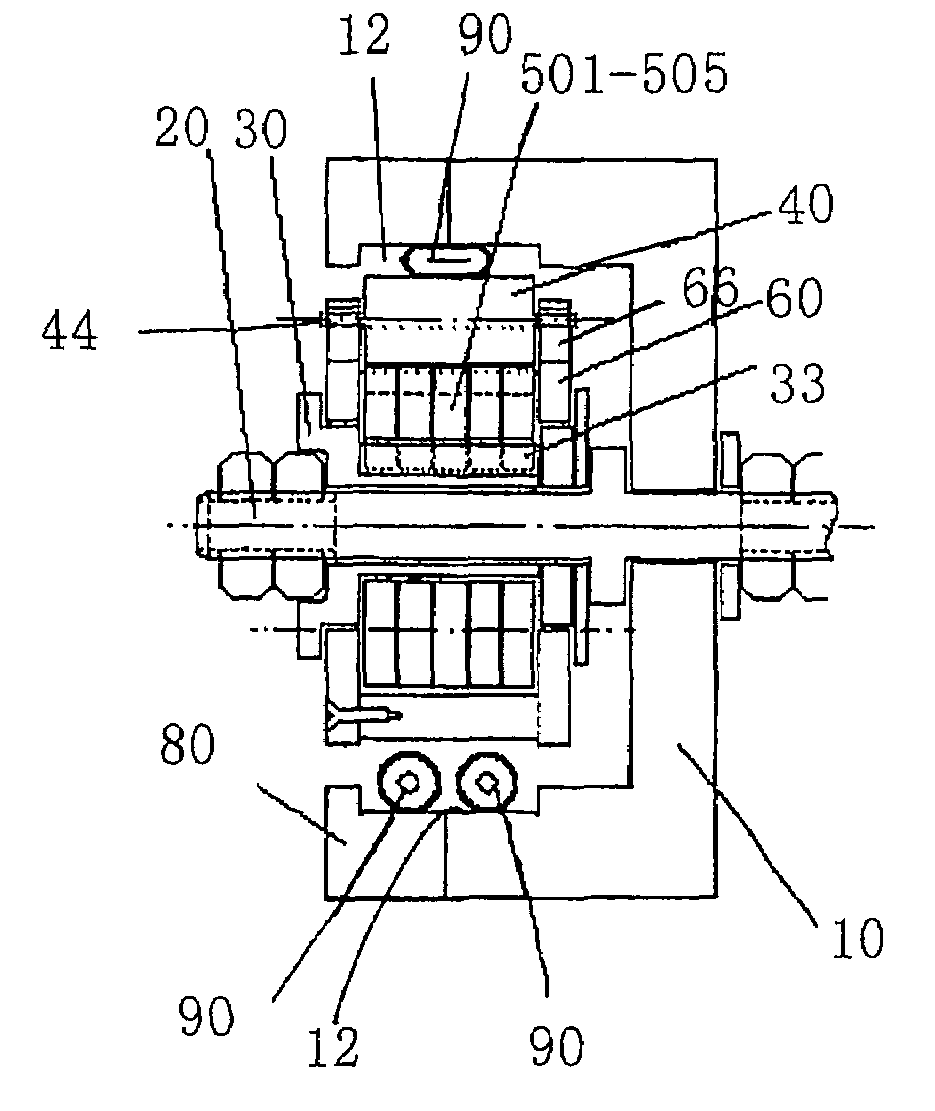
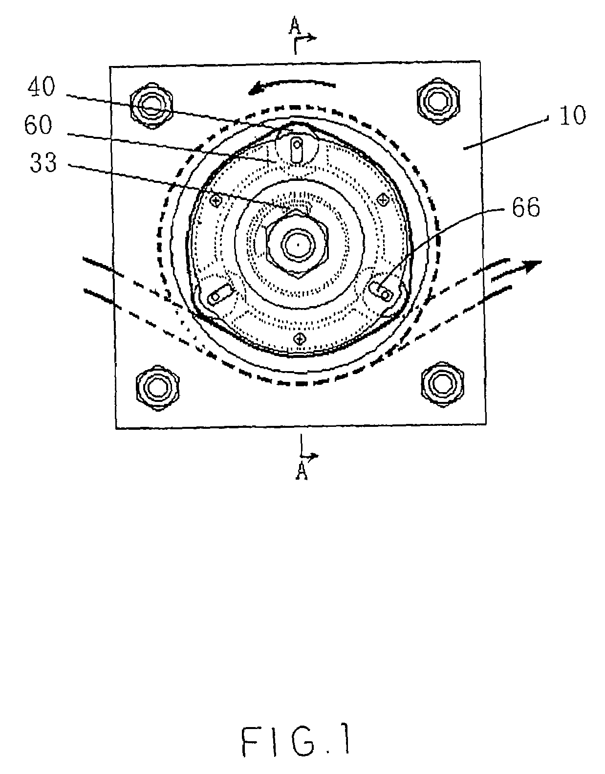
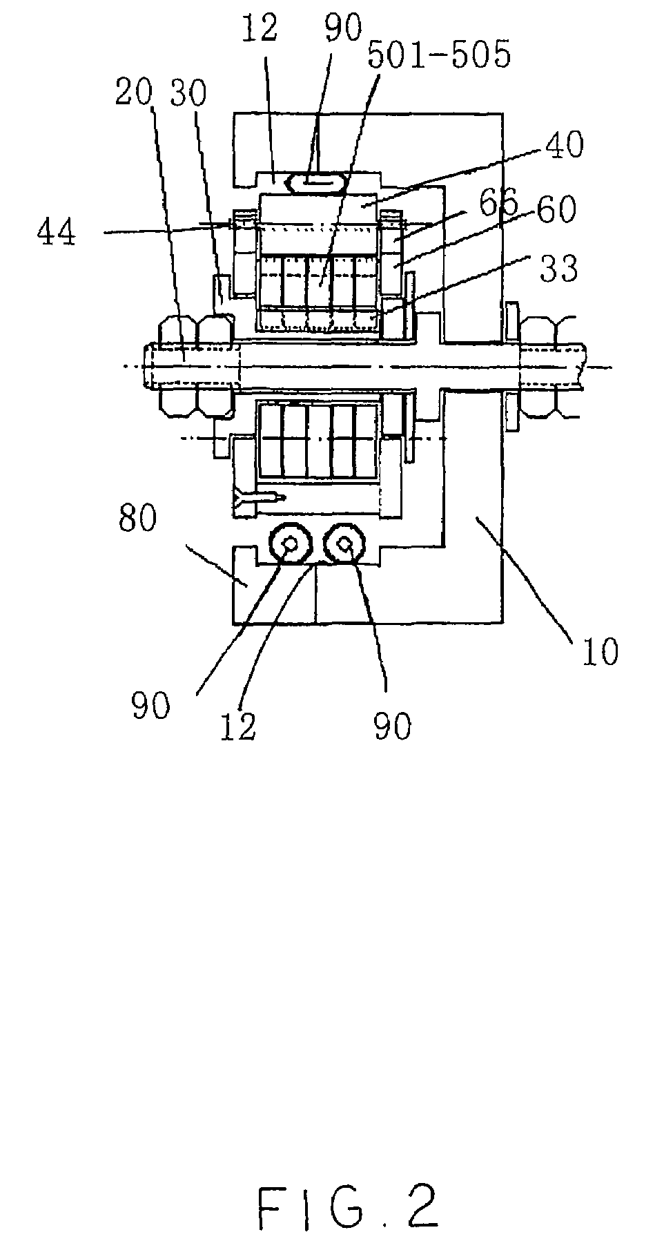
[0034]Referring to FIG. 1 and FIG. 2 of the drawings, the peristaltic pump comprises an outer casing 10, a center driving mechanism, at least two pressuring rollers 40, a retainer 60, and a flexible pump tube 90. The outer casing 10 has a guiding channel 12 formed along an inner wall of the outer casing 10 and defines a circular path therealong, a center driving mechanism supported at a center portion of the outer casing 10. There are pressuring rollers 40 spacedly and eccentrically supported at the outer casing 10. The retainer 60 is used to retain and support the pressuring roller 40. The flexible pump tube 90 made of silicon, which is adapted for allowing the liquid flowing therealong, has an operating portion extending along the guiding channel 12 of the outer casing 10. Accordingly, the pressuring rollers 40 are symmetrically and planetary supported at the outer casing in a radially movable manner. The center driving mechanism comprises a motor which drives a driving shaft 20. ...


PUM


Abstract

A peristaltic pump, for propelling liquid through a flexible pump tube, includes an outer casing having a guiding channel wherein an operating portion of the pump tube extends along the guiding channel. The peristaltic pump further includes at least two pressuring rollers supported at the outer casing in a radially movable manner which can move outwardly to press against the operating portion of the pump tube. A center driving mechanism is supported at a center portion of the outer casing to radially push the pressure rollers and to drive the pressuring rollers to concurrently rotate such that the pressuring rollers roll against the operating portion of the pump tube for continuously propelling the fluid in the pump tube in the direction of rotation.

Description

BACKGROUND OF THE PRESENT INVENTION[0001]1. Field of Invention[0002]The present invention relates to a pump for propelling liquid through a flexible tube segment, and more particularly to a peristaltic pump for propelling liquid through the flexible tube in a concealed manner to ensure the purity of the liquid during transmission and to prevent an environmental pollution of the peristaltic pump.[0003]2. Description of Related Arts[0004]The peristaltic pump is commonly used as a safe and stable liquid pumping device in many different fields such as the medical, pharmaceutical, chemical, nuclear, aviation, and environmental industries.[0005]Nowadays, conventional peristaltic pumps usually comprise an outer casing, a flexible pump tube which is adapted for allowing fluid to flow therealong, a plurality of rotating rollers spacedly supported at the outer casing at equal radial distance. The rotating rollers exert pressure on the pump tube thus to propel the liquid. A negative pressure w...

Claims


Application Information

Patent Timeline
Patent Type & Authority Patents(United States)
IPC IPC(8): F04B43/08F04B43/12F04B45/06A61M1/10F04B45/08
CPCF04B43/1253
Inventor CHENG, ZAIJUN
Owner CHENG ZAIJUN
Why Eureka
Try Eureka