Radial anti-rotation coupling

a coupling and anti-rotation technology, applied in the direction of coupling device connection, coupling parts engagement/disengagement, electrical apparatus, etc., can solve the problems of limited resilience and corresponding limited reliability, and achieve the effect of reliable operation and high resilience resistance ring

Active Publication Date: 2009-12-01
ITT MANUFACFACTURING ENTERPRISES
View PDF13 Cites 31 Cited by
  • Summary
  • Abstract
  • Description
  • Claims
  • Application Information

AI Technical Summary

Benefits of technology

[0002]In accordance with one embodiment of the invention, a connector is provided with a resistance ring lying in the annular space between a barrel and coupling nut to provide controlled resistance to nut rotation in mating and unmating directions, which results in a highly resilient resistance ring for reliable operation. The resistance ring has primarily straight ring sections that zig zag between the barrel and nut surfaces that face the annular space. The ring sections are inclined by less than 45° and preferably less than 30°, to the circumferential direction, so the inclined ring sections extend primarily circumferentially.

Problems solved by technology

The multiple closely spaced ratchets result in a ring with limited resilience and corresponding limited reliability.

Method used


Image

  • Radial anti-rotation coupling
  • Radial anti-rotation coupling
  • Radial anti-rotation coupling

Examples


Embodiment Construction

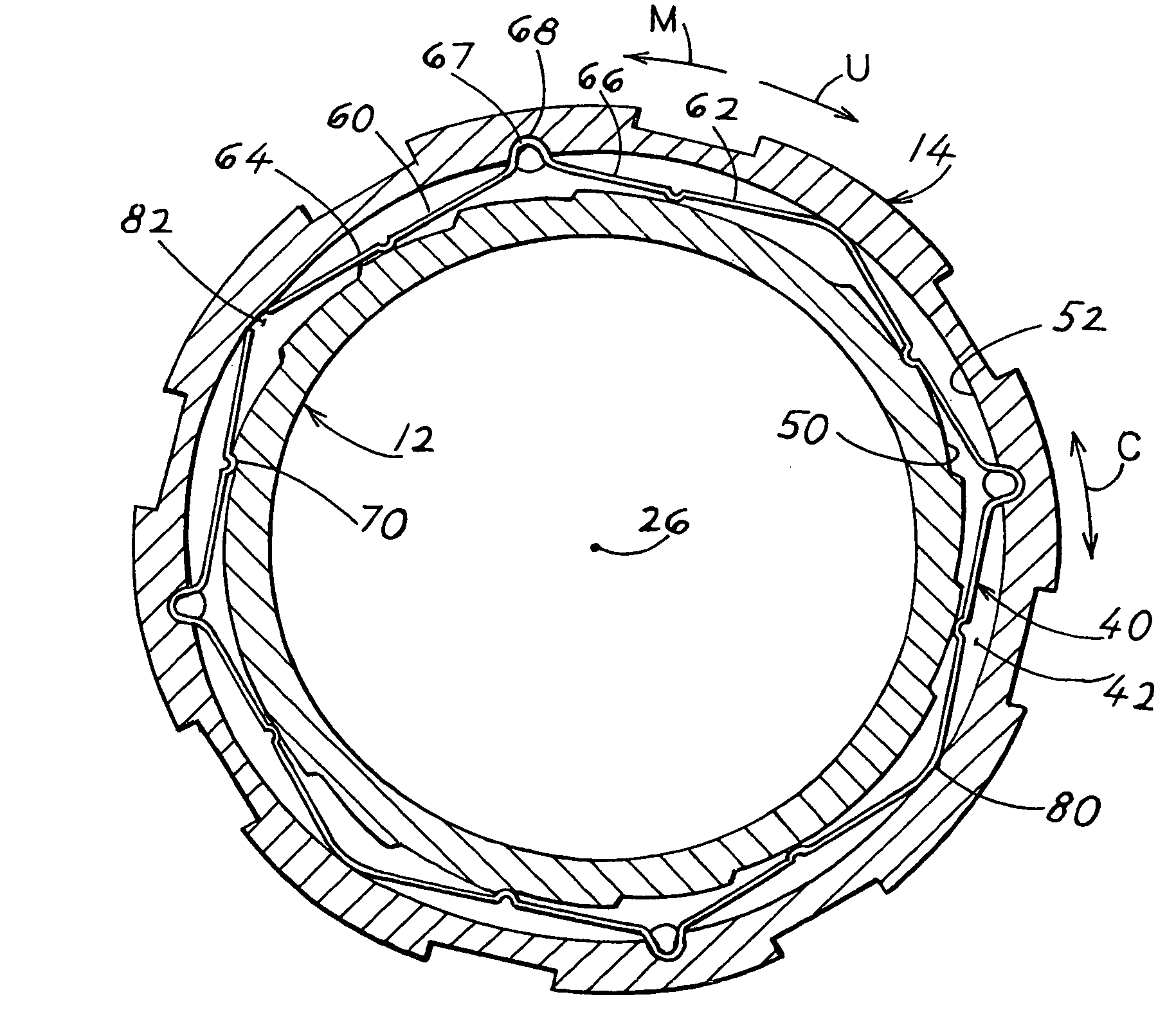
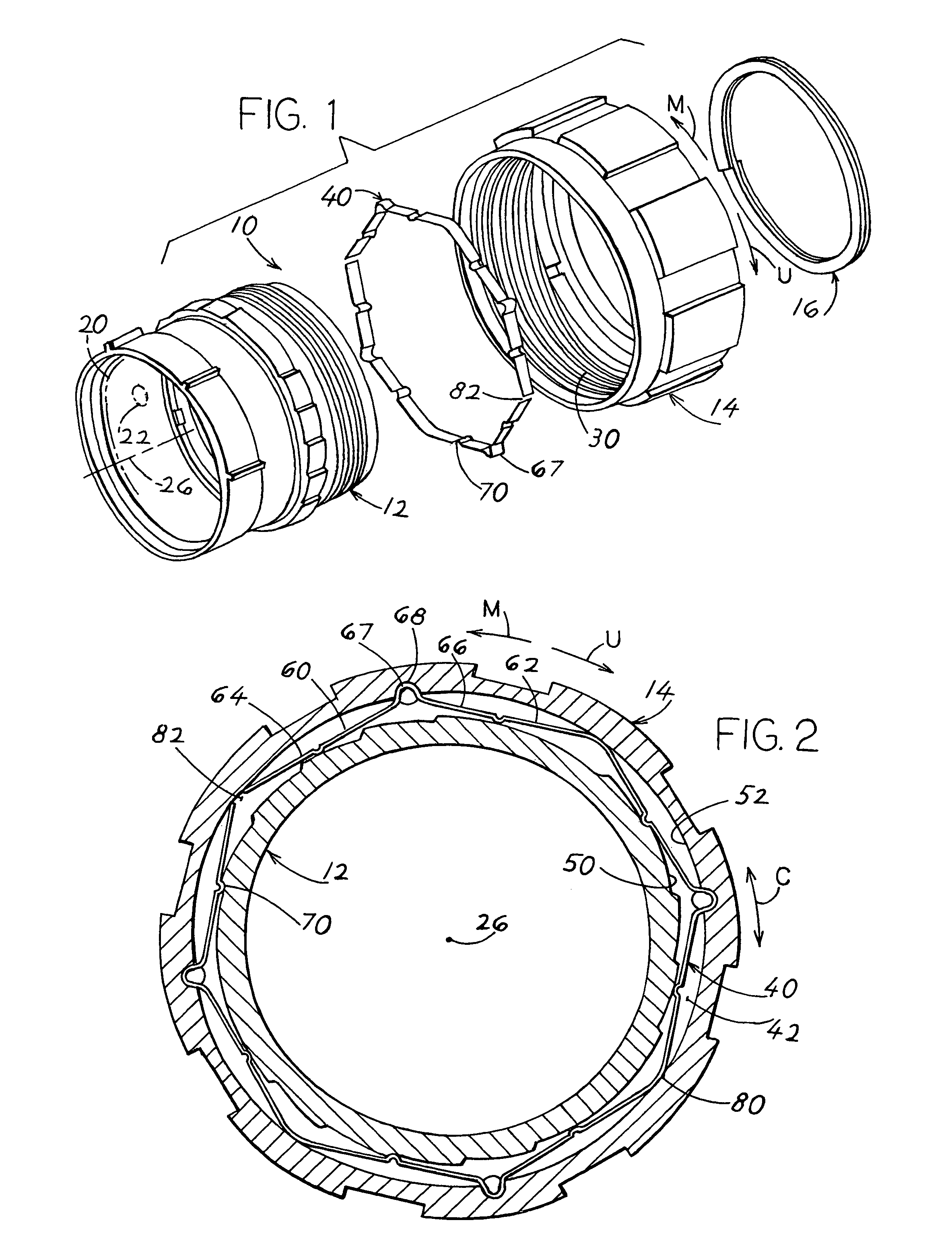
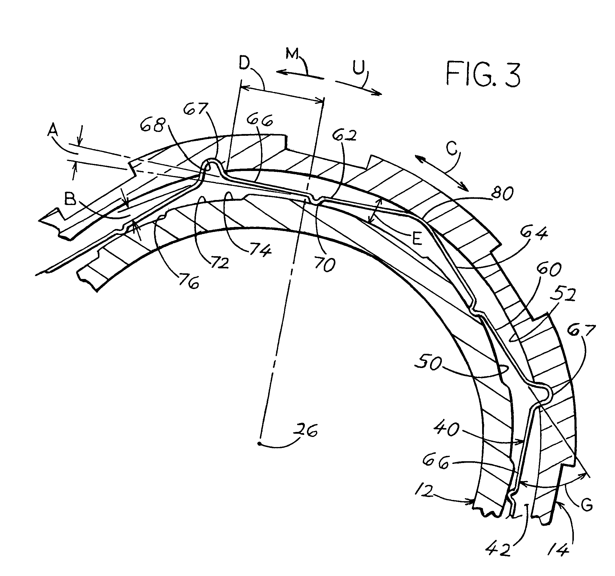
[0009]FIGS. 1 and 2 show an electrical connector 10 of the present invention which includes a barrel element 12 and a coupling nut element 14. A snap ring 16 holds the barrel and nut together while allowing the nut to rotate without limit about the barrel. The barrel 12 is used to hold a dielectric body 20 that has passages 22 that hold contacts and wires. The connector has a connector axis 26. The nut 14 is rotatable by hand about the barrel, with such rotation being used to engage internal threads 30 on the nut with threads of a mating connector (not shown) that the connector 10 mates to. During mating the nut is turned in a mating direction M, and during unmating the nut is turned in the unmating direction U.

[0010]It is desirable to provide moderate resistance to turning of the coupling nut during mating. However, it is desirable to provide a much higher resistance to turning of the nut during unmating to prevent unintentional nut turning and corresponding unintentional unmating ...


PUM


Abstract

A connector that has a coupling nut (14) that is rotatable about a barrel (12), with an annular space (42) between them, and with a resistance ring (40) lying in the annular space. The resistance ring allows the nut to rotate with moderate friction in a mating direction M, and provides higher resistance to nut rotation in an unmating direction U. The resistance ring is formed from a metal band with primarily straight band sections (60, 62, 64, 66) that alternately extend at inward and outward inclines from the circumference direction C. As a result, the resistance ring zig-zags by alternately engaging the nut surface (52) that faces the annular space, then the barrel surface (50) that faces the annular space, etc. Some of the radially outer ends of the straight sections are bent into small half circles (67) that fit into corresponding slots (68) in the nut to fix the resistance ring relative to the nut. The radially inner ends of the straight sections form bumps (70) that ride over saw teeth (74, 76) formed on the barrel surface.

Description

BACKGROUND OF THE INVENTION[0001]One type of connector includes a barrel for holding a body with passages that hold contacts (usually electrical contacts but possibly optical contacts). A coupling nut is rotatably mounted on the barrel so the nut can be rotated to thread it onto a mating second connector that has mating contacts. It is usually desirable to allow nut rotation with only a moderate resistance in a mating direction to mate the two connectors, and to provide a much higher resistance to nut rotation in the opposite unmating direction. One type of mechanism includes a ring that is mounted on the barrel and lies in the annular space between the barrel and nut, with the ring bent to form multiple closely-spaced ratchets that engage pins on the nut. The multiple closely spaced ratchets result in a ring with limited resilience and corresponding limited reliability. A resistance ring that could be easily placed in the annular space between the barrel and nut and that provided h...

Claims


Application Information

Patent Timeline
Patent Type & Authority Patents(United States)
IPC IPC(8): H01R4/38
CPCH01R13/639H01R13/622
Inventor GASTINEAU, DOUGLAS REID
Owner ITT MANUFACFACTURING ENTERPRISES
Why Eureka
Try Eureka