Combination tool with front-face recess

a technology of front-face recesses and combinatorial tools, which is applied in the direction of drilling tools, drilling tools, boring/drilling apparatus, etc., can solve the problems of undesirable thread defects, high load and associated high wear of pressing lobes, etc., and achieve the effect of producing threads very accurately

Inactive Publication Date: 2009-12-01
EMUGE WERK RICHARD GLIMPEL & FAB FUR PRAZISIONSWERKZEUGE
View PDF2 Cites 17 Cited by
  • Summary
  • Abstract
  • Description
  • Claims
  • Application Information

AI Technical Summary

Benefits of technology

[0041]The cutting region(s) and / or the thread-forming region(s) may be formed in one piece with the tool shank or may also be connected to the latter as prefabricated part(s), for example shrunk or brazed or welded or adhesively bonded or screwed in place. Furthermore, additional anti-wear coatings may be applied to the tool or its working regions. It is especially advantageous if the tool shank and the cutting part are produced from a tool steel, in particular a high-speed steel. This may be, for example a super high-speed steel (HSS steel) or a cobalt-alloy super high-speed steel (HSSE steel). The working regions are preferably produced from HSS, HSSE, HSSE-PM, carbide or a carbide alloy, in particular P grade or K grade, or cermet, or of sintered carbide, in particular of tungsten carbide or titanium nitride or titanium carbide or titanium carbonitride or aluminum oxide, or of a cutting ceramic, in particular polycrystalline boron nitride (PCBN) or of polycrystalline diamond (PCD), in particular as a coating or as, for example, strips brazed in place.
[0042]In a special embodiment, at least one thread-forming region preferably has in at least one section an outside diameter increasing, preferably conically or linearly, against the feed direction. The fact that the thread-forming region tapers in the feed direction has, for example, the advantage that the penetration of the first pressing lobes into the workpiece surface or the inner wall of the bore is facilitated. It may also be advantageous if at least one thread-forming region has an outside diameter which is uniform against the feed direction.
[0043]It is especially preferred if at least one thread-forming region has a region of increasing outside diameter against the feed direction, said region also being designated as a shaping region or initial-forming region, followed by a region of uniform outside diameter, also referred to as guide region or calibrating region. The guide region mainly serves to guide the tool in the thread, such that the force provided for the thread production in the shaping region is transmitted uniformly and thus as far as possible free of loss to the surface of the workpiece. At the same time, the guide region may have the function of smoothing and calibrating the produced thread surface or the thread flanks. As a result, the thread can be produced very accurately. In a similar manner, the cutting region may also have an initial-cutting region and a full-cutting region adjoining against the feed direction of the tool.

Problems solved by technology

However, a disadvantage with purely chipless thread production, that is to say, with thread production in which the thread is formed entirely by means of the pressing lobes, is the high loads and the associated high wear of the pressing lobes.
A disadvantage in this case, however, is that workpiece chips produced by the cutting region may be pressed into the thread by the following thread-forming region, which may lead to undesirable defects in the thread.

Method used


Image

  • Combination tool with front-face recess
  • Combination tool with front-face recess
  • Combination tool with front-face recess

Examples


Embodiment Construction

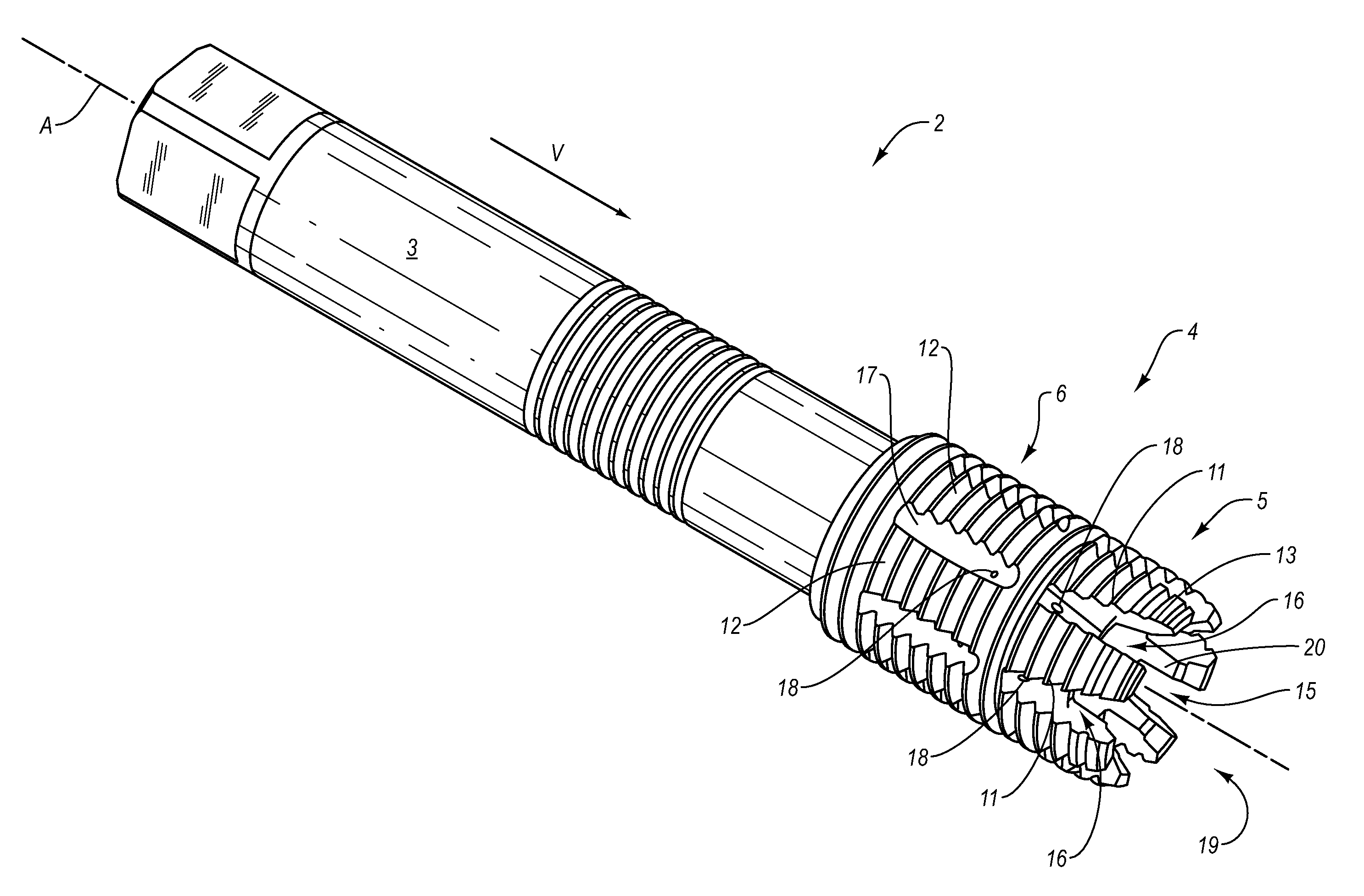
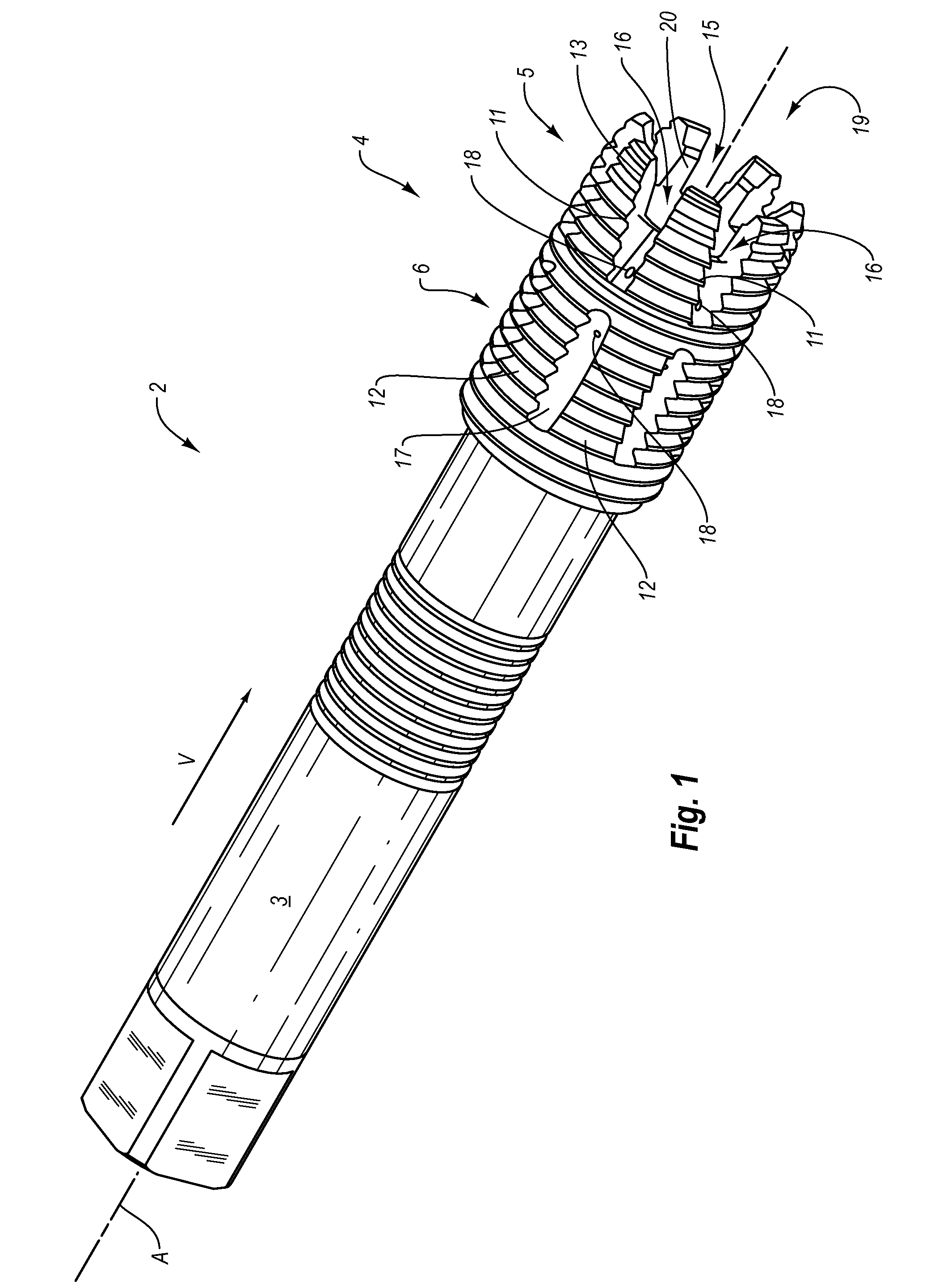
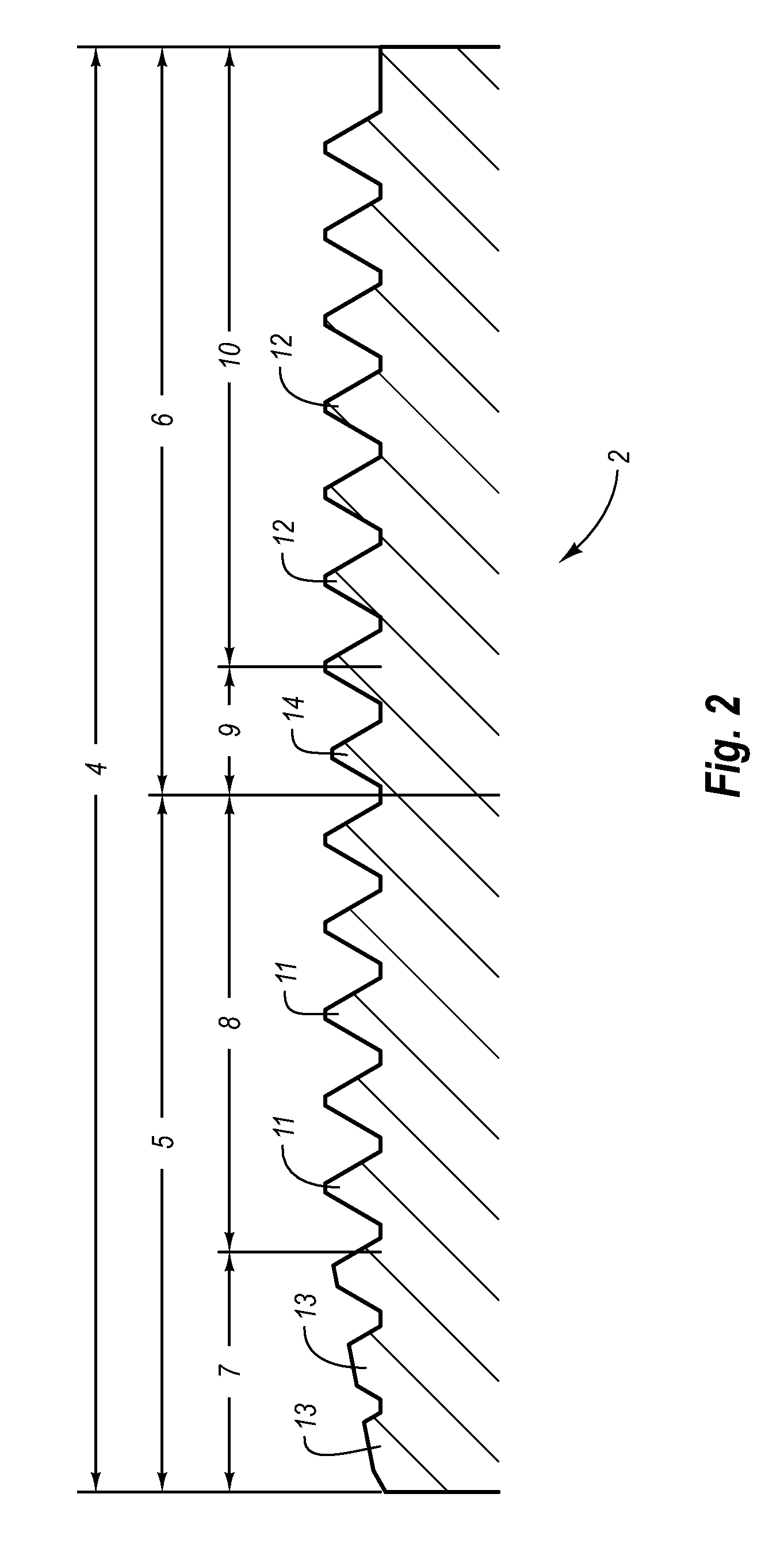
[0050]FIG. 1 shows an exemplary embodiment of a tool 2 according to the invention in a perspective illustration, having a tool shank 3, a working head 4 arranged on the tool shank 3, a tool longitudinal axis A and an envisaged feed direction V for processing a workpiece. FIG. 2 shows, in a longitudinal section, part of the working head 4 of the tool 2 shown in FIG. 1.

[0051]The working head 4 of the tool 2 can be designed to be firmly connected to the shank 3, in particular in one piece with the shank 3. However, it is likewise possible to releasably-connect the working head 4 to the shank 3, for example by the working head 4 being designed as a detachable and thus interchangeable slip-on part.

[0052]The tool 2 is a combination tool, to be precise a thread-cutting / forming tool. The working head 4 comprises a cutting region 5, which may also be designated as cutting part, and a thread-forming region 6, which may also be designated as forming part. The cutting region 5 and the thread-fo...


PUM

PropertyMeasurementUnit
distanceaaaaaaaaaa
areaaaaaaaaaaa
lengthaaaaaaaaaa

Abstract

A tool for producing a thread such as an internal thread, can include at least one cutting region having at least one cutting edge and at least one thread-forming region. In general, the cutting region(s) and the thread-forming region(s) are coupled or connected to one another in such a way that they are rotatable or rotate together about a tool axis. In addition, at least one cutting region is at least partly formed on a front-face tool end and / or adjacent to a front-face tool end. Furthermore, a front-face recess that is configured for receiving chips is formed on the front-face tool end.

Description

CROSS-REFERENCE TO RELATED APPLICATIONS[0001]The present invention claims the benefit of priority under 35 U.S.C. § 119 to German Patent Application No. 10 2006 010 651.2, filed on Mar. 6, 2006, having a translated title of “COMBINATION TOOL WITH FRONT-FACE RECESS,” which is incorporated herein by reference in its entirety.BACKGROUND OF THE INVENTION[0002]1. The Field of the Invention[0003]The invention relates to a tool for producing a thread, in particular an internal thread.[0004]2. Background and Relevant Art[0005]For thread production, in particular for producing threads for screwed connections, tools working with a cutting action and tools working with a chipless action are known.[0006]Tools working with a cutting action have cutting edges. This group includes drills, which process a workpiece in particular with a continuous cut or with continuous engagement of the cutting edges in the material, and milling cutters, which process the workpiece in particular with a discontinuou...

Claims


Application Information

Patent Timeline
Patent Type & Authority Patents(United States)
IPC IPC(8): B21J13/02
CPCB23G5/06B23G7/02Y10T408/9048B23G2240/08B23G2200/42
Inventor GLIMPEL, HELMUTHECHTLE, DIETMAR
Owner EMUGE WERK RICHARD GLIMPEL & FAB FUR PRAZISIONSWERKZEUGE
Why Eureka
Try Eureka