
Apparatus comprising a single photon photodetector having reduced afterpulsing and method therefor

a single-photon, afterpulsing technology, applied in the direction of optical radiation measurement, instruments, x/gamma/cosmic radiation measurement, etc., can solve the problem of high dark count rate of prior-art single-photon photodetectors

Active Publication Date: 2009-12-01
LG INNOTEK CO LTD
View PDF2 Cites 1 Cited by
  • Summary
  • Abstract
  • Description
  • Claims
  • Application Information

AI Technical Summary

Benefits of technology

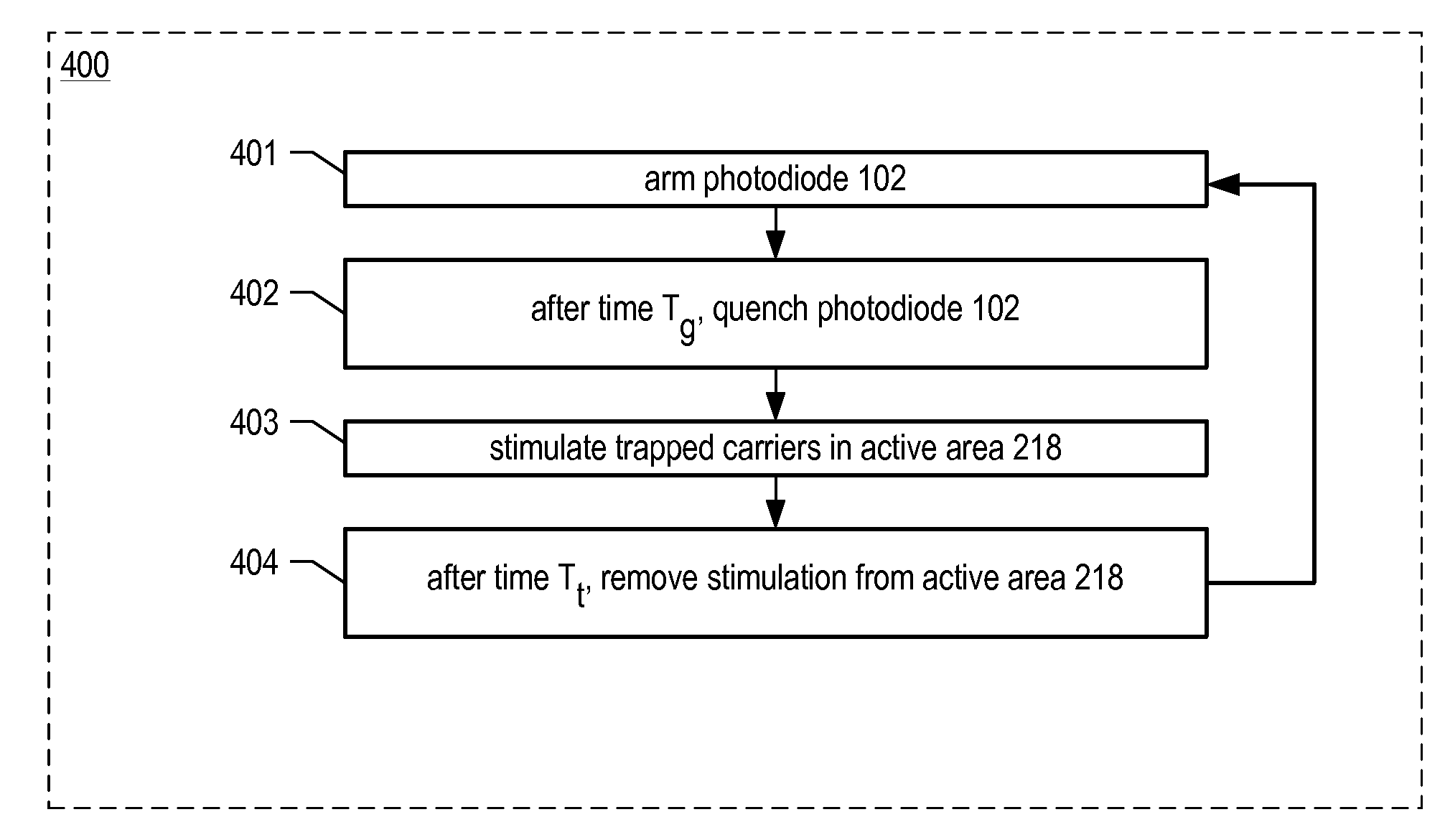
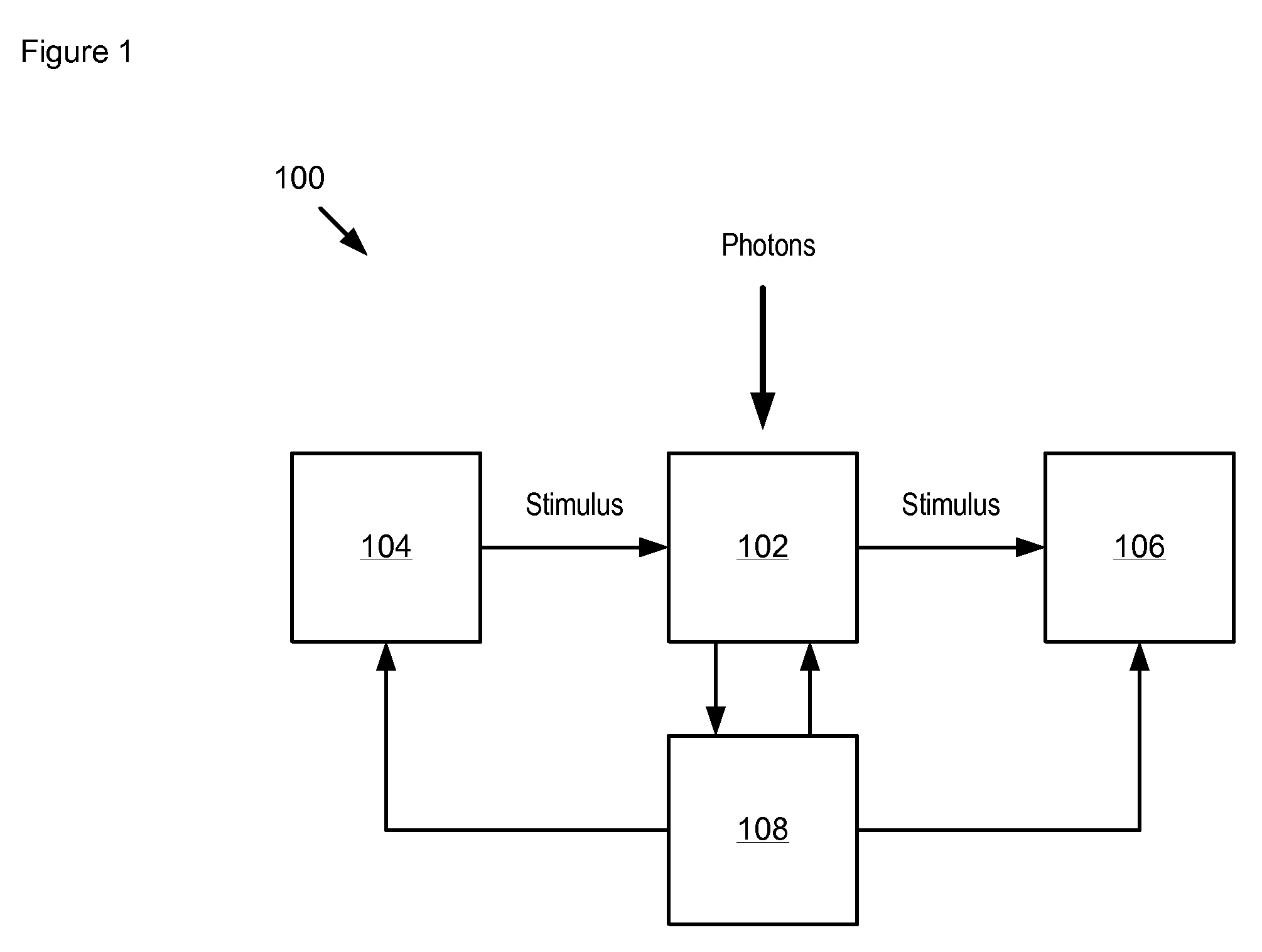
[0015]In accordance with the illustrative embodiment of the present invention, trapped carriers in the photodetector are excited by a pulse of stimulating energy, such as a thermal pulse. This proactive excitation of trapped carriers clears energy trap states. This reduces the probability of random emissions of these carriers, as might otherwise occur in the absence of the stimulus (e.g., during conventional operation as a single-photon detector, etc.). As a result, the dark count rate of the photodetector during single-photon operation is reduced.
[0016]Embodiments of the present invention, like the prior art, use an avalanche photodetector that is biased above its breakdown voltage to detect the incidence of a single photon. Like the prior art, some embodiments of the present invention proactively excite carriers that are in energy trap states, thereby reducing afterpulsing. But unlike the prior art, in the illustrative embodiment of the present invention, trapped carriers are only temporarily excited.
[0017]More particularly, in the prior art, photodetectors have been operated at an elevated temperature to stimulate the emission of trapped carriers from energy trap states. These photodetectors remain at this elevated temperature during operation as a single-photon detector. As a result, prior-art single-photon photodetectors are subject to high dark count rates. In contrast, the present invention applies only a pulse of thermal energy to the photodetector to temporarily raise the temperature of a photodetector. The photodetector is not operated in single-photon detection mode during the application of the stimulating pulse. The thermal pulse substantially clears energy trap states of carriers so that the photodetector has a reduced dark count rate when it is subsequently operated as a single-photon photodetector.

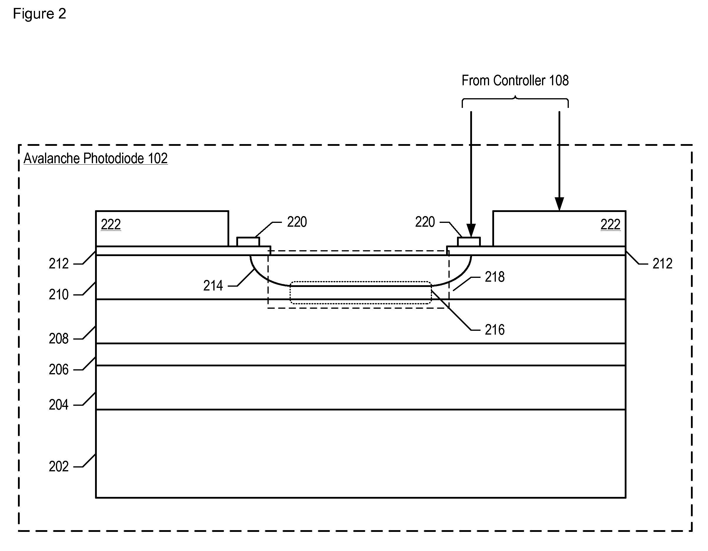
Problems solved by technology

As a result, prior-art single-photon photodetectors are subject to high dark count rates.

Method used


Image

  • Apparatus comprising a single photon photodetector having reduced afterpulsing and method therefor
  • Apparatus comprising a single photon photodetector having reduced afterpulsing and method therefor
  • Apparatus comprising a single photon photodetector having reduced afterpulsing and method therefor

Examples


Embodiment Construction

[0023]The following terms are defined for use in this Specification, including the appended claims:[0024]Monolithically-integrated means formed either: (1) in the body of a layer or substrate, typically by etching into the layer or substrate or; (2) on the surface of the layer or substrate, typically by patterning layers disposed on the surface.[0025]Thermal-cycling means temporarily changing a temperature to cause an effect. An example of thermal-cycling is the rapid-thermal annealing of a substrate to induce crystal growth or stress relaxation.[0026]Pulse means a brief sudden change in a normally constant quantity. Examples of pulses include, without limitation: (1) a thermal pulse, wherein a short rapid increase in the temperature of an element or portion of an element is produced; and (2) a voltage pulse, wherein a short rapid increase in a voltage is produced.[0027]Multiplication region means a region of an avalanche photodetector wherein avalanche gain predominantly occurs.

[00...


PUM


Abstract

A single-photon detector is disclosed that provides reduced afterpulsing without some of the disadvantages for doing so in the prior art. An embodiment of the present invention provides a stimulus pulse to the active area of an avalanche photodetector to stimulate charges that are trapped in energy trap states to detrap. In some embodiments of the present invention, the stimulus pulse is a thermal pulse.

Description

FIELD OF THE INVENTION[0001]The present invention relates to avalanche photodetectors in general, and, more particularly, to single-photon avalanche photodetectors.BACKGROUND OF THE INVENTION[0002]A semiconductor photodetector generates a free-carrier pair (electron-hole) when it absorbs a photon. When the photodetector is subjected to an electric field (by the application of a bias voltage to the photodetector), free-carriers generated in the photodetector give rise to a macroscopic electric current.[0003]A useful photodetector is characterized by high overall efficiency and high sensitivity. Efficiency can be defined as the number of free carriers that are generated per incident photon. Consequently, high efficiency implies a high generated current for a given incident optical power. Sensitivity is characterized by the minimum optical signal that gives rise to a current that can be distinguished from the background current due to noise (e.g., dark current, thermal noise, Johnson n...

Claims


Application Information

Patent Timeline
Patent Type & Authority Patents(United States)
IPC IPC(8): H01L31/058
CPCH01L31/1075
Inventor ITZLER, MARK ALLENBEN-MICHAEL, RAFAELRANGWALA, SABBIR SAJJAD
Owner LG INNOTEK CO LTD
Learn More