Slew rate control for output signals

Active Publication Date: 2009-12-01
XILINX INC
View PDF5 Cites 21 Cited by
  • Summary
  • Abstract
  • Description
  • Claims
  • Application Information

AI Technical Summary

Benefits of technology

[0009]A method and apparatus are disclosed that allow the slew rate of an output driver to be controlled and selectively adjusted so that the output driver is compatible with other IC circuits and devices having different specified I/O signal switching speeds and characteristics. In accordance with the present invention, an output circuit for an integrated circuit (IC) device, such as an FPGA, has an output terminal for providing an output signal and includes a pre-driver circuit that is configurable to adjust the slew rate of the output signal to a desired level. For some embodiments, the output driver includes a PMOS output transistor coupled between a supply voltage and the output terminal, and includes an NMOS output transistor coupled between the output terminal and ground potential. For some embodiments, the pre-driver circuit includes first and second pre-driver circuits. The first pre-driver circuit has a

Problems solved by technology

However, the fast I / O signal switching speeds typically exhibited by FPGA devices are not suitable for all applications, and in some cases may even preclude the deployment of FPGA devices in systems that would otherwise be ideal for FPGA devices.
For example, although the configurable nature of FPGA devices renders the devices ideal for performing test and de-bug operations for embedded systems, the deployment of FPGA devices in a system's circuit boards that are not optimized high-speed I / O signal switching speeds (e.g., such boards are commonly referred to as “breadboards”) can undesirably cause logic upset of logic components included in the system because the signal switching speed of the FPGA device is too fast.
Thus, if the specified slew rate is not met by the FPGA's output driver, the FPGA device may be incompatible with the other chips or devices.
Further, although higher operating frequencies are generally desired, if the FPGA output driver's slew rate is too high, undesirable noise may be introduced into the output signal.
However, providing different versions of an FPGA device increases costs and reduces the economies of scale that have made FPGA devices a successful, cost-effective alternative to application-specific integrated circuit (ASIC) devices.
Because the slew rate of an output signal is affected by the device's operating voltage (e.g., increasing the operating voltage typically decreases transistor propagation delays and thus increases the output signal slew rate), changing the operating voltage can undesirably change the output signal slew rate.

Method used


Image

  • Slew rate control for output signals
  • Slew rate control for output signals
  • Slew rate control for output signals

Examples


Embodiment Construction

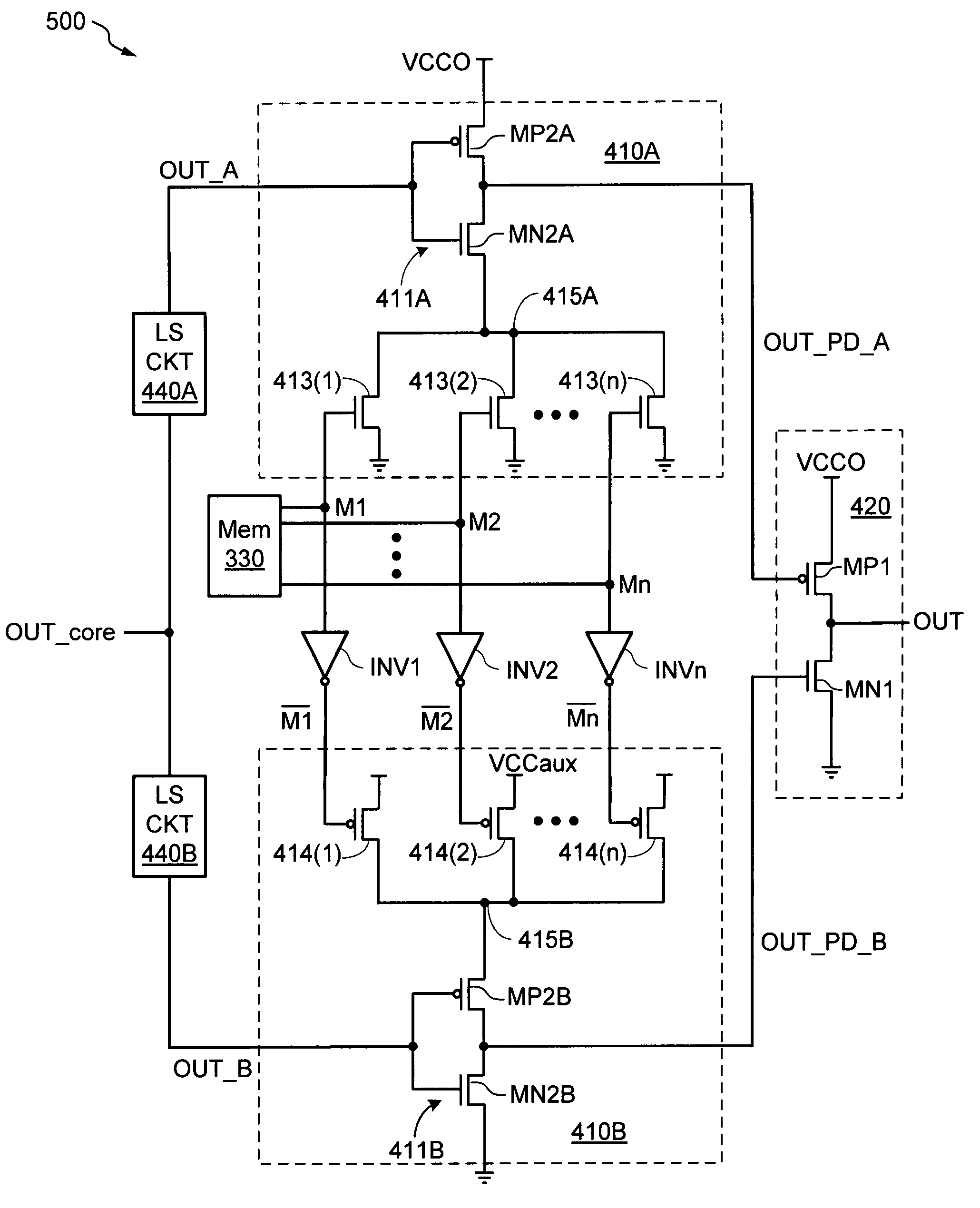
[0020]Embodiments of the present invention are described below in the context of an exemplary FPGA architecture for simplicity only. It is to be understood that present embodiments are equally applicable to other PLD architectures such as FPGAs and complex PLDs, and to other types of integrated circuits including, for example, application-specific integrated circuit (ASIC) devices. In the following description, for purposes of explanation, specific nomenclature is set forth to provide a thorough understanding of the present invention. In other instances, well-known circuits and devices are shown in block diagram form to avoid obscuring the present invention unnecessarily. Further, the logic states of various signals described herein are exemplary and therefore may be reversed or otherwise modified as generally known in the art. Additionally, the interconnection between circuit elements or blocks may be shown as buses or as single signal lines. Each of the buses may alternatively be ...


PUM


Abstract

An output circuit allows the slew rate of its output signal to be selectively adjusted. The output driver circuit includes an output driver and pre-driver circuits. The output driver includes an output transistor coupled between a first supply voltage and the output terminal. The pre-driver circuit selectively adjusts a series resistance between the output transistor's gate and a second supply voltage in response to mode control signals.

Description

FIELD OF INVENTION[0001]The present invention relates generally to integrated circuits, and more specifically to voltage regulation in integrated circuits.DESCRIPTION OF RELATED ART[0002]A programmable logic device (PLD) is a general-purpose device that can be programmed by a user to implement a variety of selected functions. One type of PLD is the Field Programmable Gate Array (FPGA), which typically includes an array of configurable logic blocks (CLBs) surrounded by a plurality of input / output blocks (IOBs). The CLBs are individually programmable and can be configured to perform a variety of logic functions on a few input signals. The IOBs can be configured to drive output signals from the CLBs to external pins of the FPGA and / or to receive input signals from the external FPGA pins. The FPGA also includes a programmable interconnect structure that can be programmed to selectively route signals among the various CLBs and IOBs to produce more complex functions of many input signals....

Claims


Application Information

Patent Timeline
IPC IPC(8): H03K19/0175
CPCH03K19/018585
Inventor LI, RICHARD C.YOUNG, PHILLIP A.WALSTRUM, JR., JAMES A.
Owner XILINX INC
Why Eureka
Try Eureka