
System and method for designing a network

a packet network and packet technology, applied in the field of packet network system and method, can solve the problems of traffic sensitive to delay over the network, delay-sensitive applications may not receive sufficient resources to satisfy delay requirements, etc., and achieve the effect of high utilization

Inactive Publication Date: 2009-12-01
AT&T INTPROP II L P
View PDF25 Cites 9 Cited by
  • Summary
  • Abstract
  • Description
  • Claims
  • Application Information

AI Technical Summary

Benefits of technology

"The invention provides a method and apparatus for designing a network that supports various types of applications while maintaining high utilization. The network is designed based on the volume of traffic and maximum delays for each link. The bandwidth required for each link is determined based on the current traffic routing and maximum delay. Link lengths are determined based on the marginal cost of the link with respect to the total traffic that is routed on it. The same set of link lengths is used for every class of traffic based on a weighted sum of the link lengths determined separately for each traffic class. The network design can be systematically examined to determine if eliminating or adding any given link would improve the cost or other relevant metric of the network."

Problems solved by technology

Such traffic is sensitive to delay over the network.
Because both delay-sensitive and delay-tolerant applications are being served together, delay-sensitive applications may not receive sufficient resources to satisfy delay requirements.

Method used


Image

  • System and method for designing a network
  • System and method for designing a network
  • System and method for designing a network

Examples


Embodiment Construction

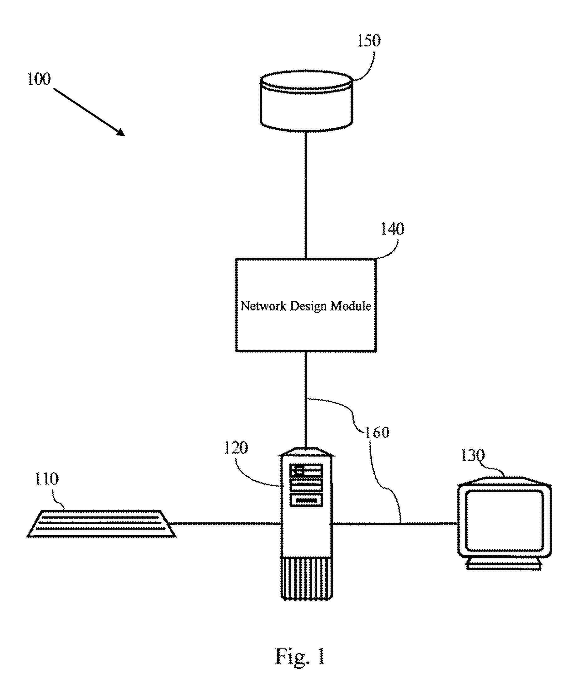
[0017]FIG. 1 is an exemplary block diagram of a system 100 according to one embodiment of the invention. The system 100 may include an input device 110, a main central processing unit (CPU) 120, an output device 130, a network design module 140, a database 150 and a bus 160. The input device 110 may include a keyboard, keypad, scanner, microphone or any other device that is useful for inputting data to a system. The output device 130 may include a monitor, an LCD display, a printer, a modem or any other device that is useful for outputting data.

[0018]The main CPU 120 may include a processor, a personal computer, a notebook computer, a mainframe computer, or any other device that is useful for processing data. “the database 150 may be stored computer-readable media such as RAM, ROM, CD-ROM, a hard disk drive, a floppy disk drive, or any other memory device that is useful for storing data.” The bus 160 may include a local bus on a motherboard, a local area network (LAN), a wide area n...


PUM


Abstract

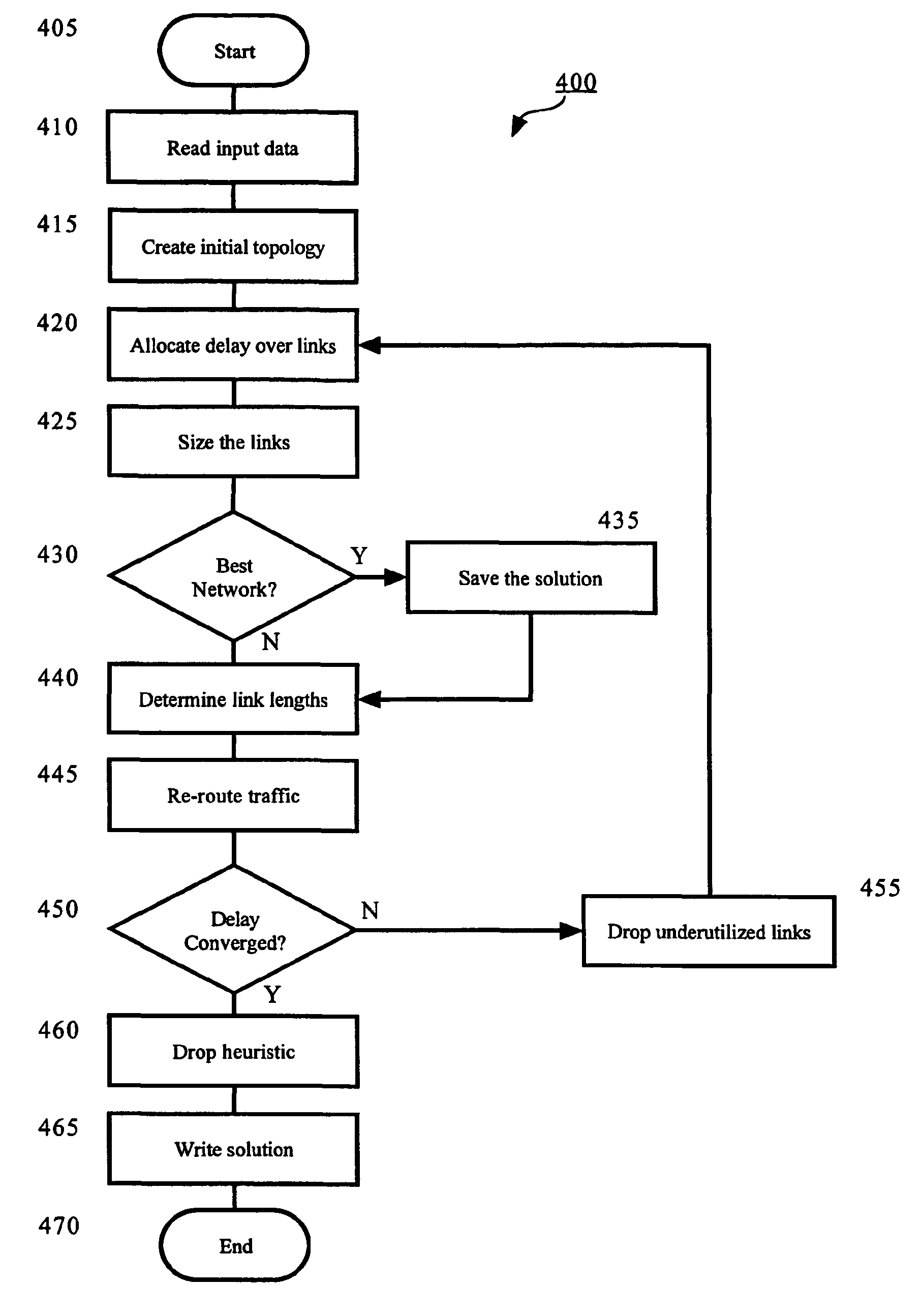
A system and computer-readable medium for designing a network are disclosed. A network is designed by a system having modules configured to perform steps that generate the network wherein nodes originate and terminate traffic to keep delay related to node-to-node delay-sensitive communication below a threshold. The computer-readable medium stores instructions for controlling a computing device to design the network. The instructions comprise obtaining an initial network topology including links and traffic routing based on a volume of traffic, allocating a maximum delay to each link in the network topology in proportion to a square root of an imputed cost for each of the links, sizing a bandwidth required for each of the links based on a current traffic routing and at least one of a maximum delay allocated to the link, determining link lengths and rerouting traffic according to shortest paths with respect to the determined link lengths.

Description

PRIORITY CLAIM[0001]The present application claims priority to U.S. application Ser. No. 10 / 706,432 filed Nov. 12, 2003, which is a continuation of U.S. Pat. No. 6,697,334, the contents of which are incorporated herein by reference.FIELD OF INVENTION[0002]The present invention is directed to a method and apparatus for designing a packet network that supports Quality of Service.DESCRIPTION OF RELATED ART[0003]There has been a shift in the design of communication networks from diverse data networks, each of which is dedicated to a class of applications, to unified networks, typically utilizing Internet Protocol (IP). As a result, an increased volume of diverse data traffic is being carried over IP networks. For example, the increased traffic may include mission-critical applications such as stock investment transactions and other forms of electronic commerce. The increased traffic may also include other emerging applications, such as voice and video data. Such traffic is sensitive to ...

Claims


Application Information

Patent Timeline
Patent Type & Authority Patents(United States)
IPC IPC(8): H04L12/26H04J3/14H04L12/24
CPCH04L41/145H04L41/5009H04L43/16H04L43/0852H04L43/0876H04L41/5025
Inventor KLINCEWICZ, JOHN GREGORYSCHMITT, JAMES ANTHONYWONG, RICHARD TEKEE
Owner AT&T INTPROP II L P
Learn More