Single stage dual-entry centrifugal compressor, radial turbine gas generator

a gas generator and centrifugal compressor technology, applied in the direction of positive displacement liquid engines, liquid fuel engines, piston pumps, etc., can solve the problems of difficult to achieve the pressure ratio of 12:1, and achieve the effect of less compact configuration, high efficiency, and higher losses

Active Publication Date: 2009-12-08
OPRA TECH
View PDF7 Cites 13 Cited by
  • Summary
  • Abstract
  • Description
  • Claims
  • Application Information

AI Technical Summary

Benefits of technology

[0008]The present invention constitutes an advanced aerodynamic and structural solution to efficiently accomplish in one stage, performance that would otherwise require multiple compressor stages, higher losses, and costlier, less-compact configurations. Moreover, radial compressor-turbine configurations according to the current invention are able to demonstrate at least 30% efficiency in a power range substantially lower (about one third) of the larger, axial turbines. The aerodynamic design of the gas generator with a double entry, high pressure ratio centrifugal compressor coupled to an uncooled radial turbine will have lower losses than configurations using axial rotor components. Radial gas generators and engines according to the present disclosure thus have a performance “window” below the optimum operating advantage of axial component machines.
[0011]Hence, for a given mass flow and speed (RPM), the dual-entry compressor can be configured in accordance with the present invention, to handle the flow within acceptable Mach Numbers and losses. The requirement of a 12:1 pressure ratio would be very difficult to achieve with conventional single-entry centrifugal compressors while maintaining a close clearance between the impeller and the housing. Configuring the dual-entry compressor to be symmetrical substantially avoids shape distortion at high RPM's, the so-called “flowering” effect, with consequent probability of rubbing.

Problems solved by technology

The requirement of a 12:1 pressure ratio would be very difficult to achieve with conventional single-entry centrifugal compressors while maintaining a close clearance between the impeller and the housing.

Method used


Image

  • Single stage dual-entry centrifugal compressor, radial turbine gas generator
  • Single stage dual-entry centrifugal compressor, radial turbine gas generator
  • Single stage dual-entry centrifugal compressor, radial turbine gas generator

Examples


Embodiment Construction

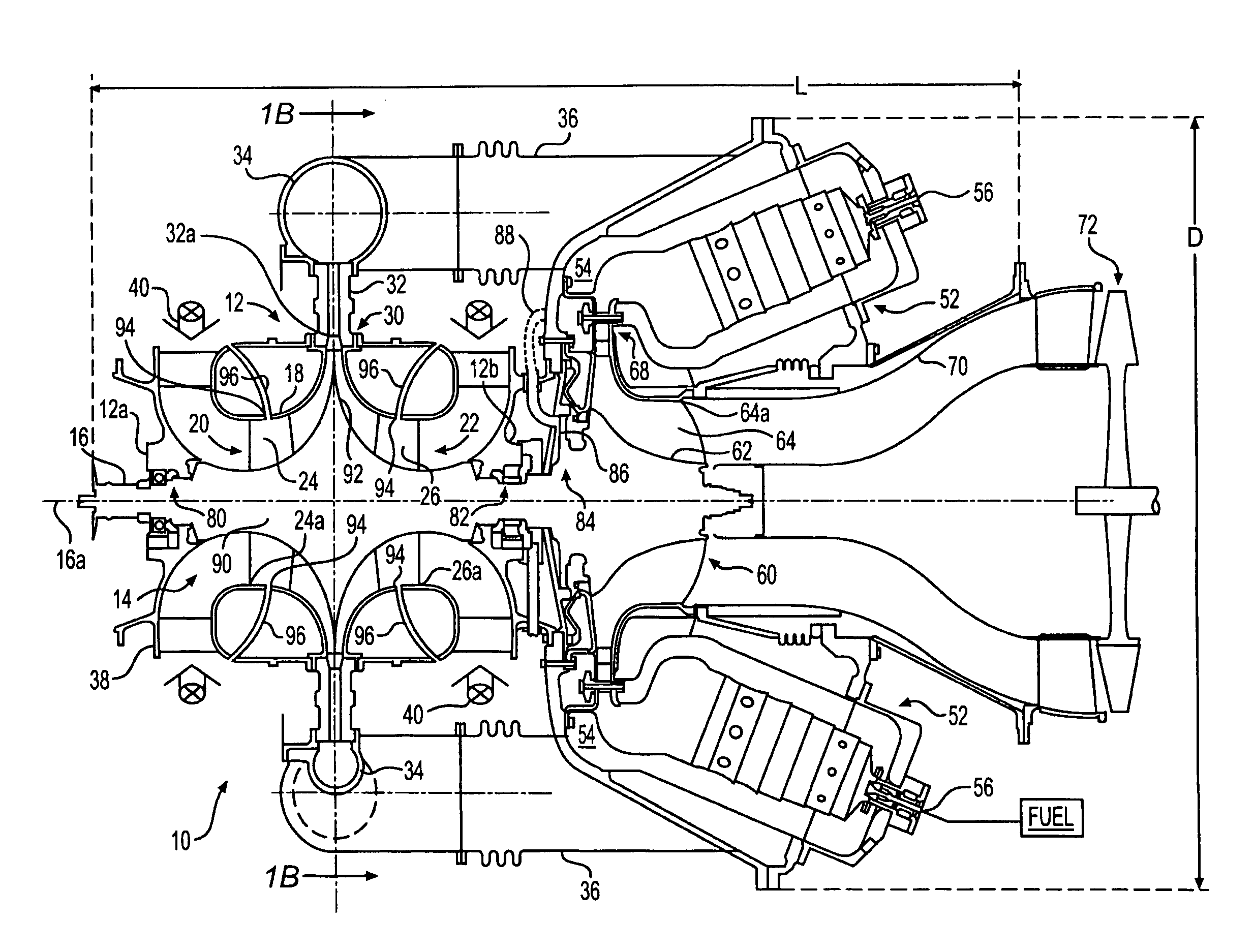
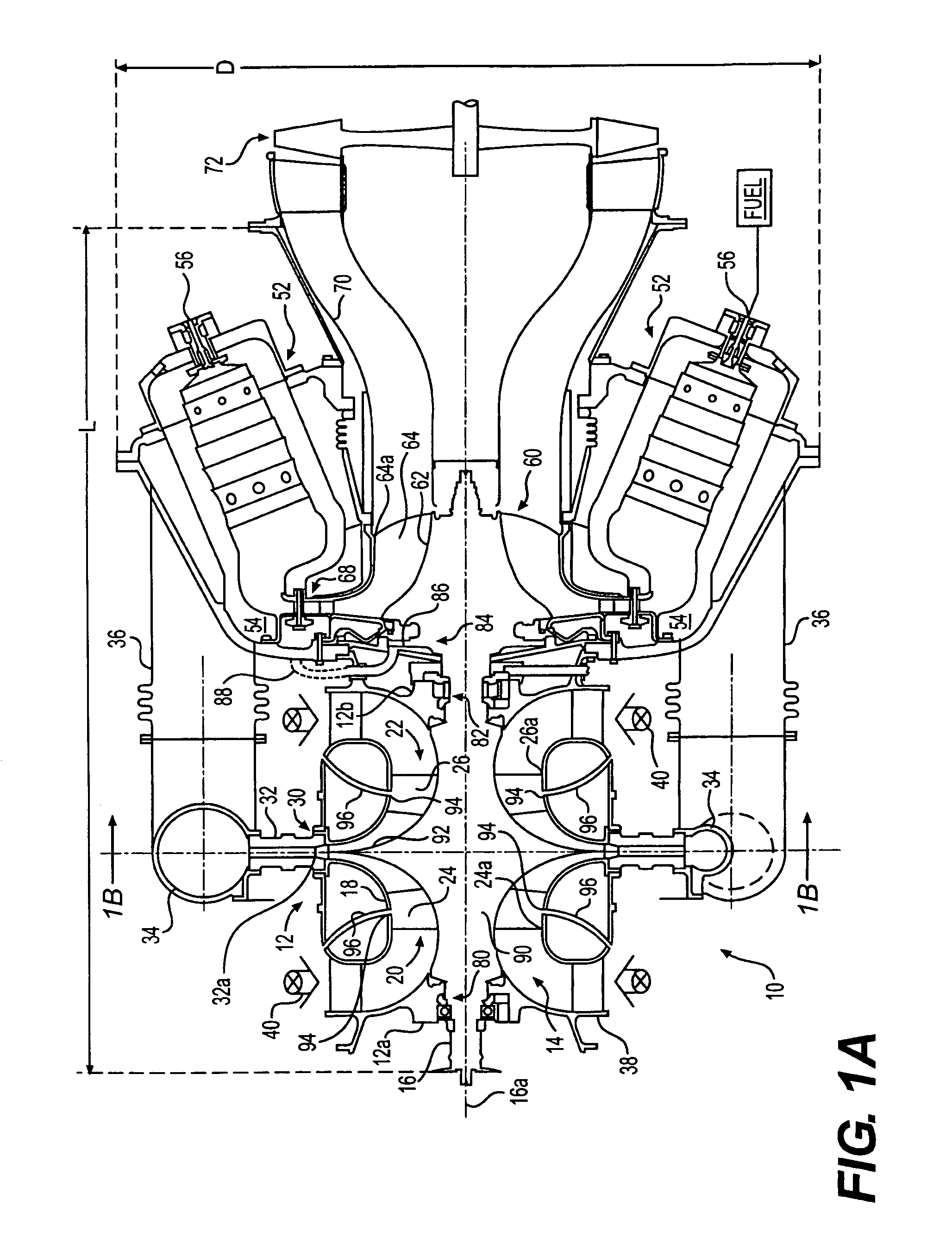
[0020]In accordance with an aspect of the present disclosure, the gas turbine gas generator includes a rotatable shaft defining an axial direction and a radial direction, and a single compressor stage having a dual-entry centrifugal compressor mounted on the shaft and having a housing and a bladed impeller. The impeller defines with the housing a pair of axially directed inlets and a single radially directed outlet. As embodied herein and depicted in FIG. 1A, gas turbine gas generator designated generally by 10 includes dual-entry high pressure ratio compressor module 12 having impeller 14 mounted for rotation with shaft assembly 16 about axis 16a. Dual-entry compressor 12 also includes housing 18 which together with impeller 14 define a pair of flow-symmetric, axially opposed inlets 20, 22 for directing air to compressor blade assemblies 24, 26 of impeller 14. Dual-entry compressor 12 has a single, annular, radially directed compressor outlet 30 operatively connected to annular dif...


PUM


Abstract

A compact, single shaft gas turbine gas generator uses a high pressure ratio dual-entry single stage centrifugal compressor, can combustors, and a radial inflow turbine with the compressor configured to achieve an overall pressure ratio of about 12:1 or greater and Mach Numbers less than or equal to about 1.4. The radial inflow turbine is configured to provide an expansion ratio of about 4:1 to about 5:1, to provide partially expanded combustion gases to a free-power turbine or an expansion nozzle, in a work-producing engine configuration. A ball bearing assembly in front of the compressor is used in conjunction with a thrust piston assembly to take up turbine thrust load, while a radial tilt pad bearing assembly is used in front of the turbine. A collector with scroll-shaped sector portions collects compressed air from an annular vaned diffuser, and respective crossover ducts channel the collected diffused compressed air from each sector portion to a plenum feeding can combustors. Bleed systems at each compressor inlet provide increased diffuser stability margins. Gas turbine engines configured with the above gas generator may provide 30% thermal efficiency or more in a rated power range of about 4 Mw or less.

Description

BACKGROUND[0001]1. Field of the Invention[0002]This invention relates to gas turbine gas generators, and more particularly to structurally compact, high performance gas turbine gas generators using centrifugal compressors and radial inflow turbines. This invention also relates to gas turbine engines using such gas generators.[0003]2. Description of the Prior Art[0004]There is a continuing need for gas turbine power plants as alternatives for diesel engines, for instance, for vehicular and other applications where a compact, lightweight engine is required. Practical experience has shown that substantial space and weight savings are available using conventional gas turbines. However, existing gas turbine engines in the small / medium power range, e.g. about 4 megawatts (“Mw”) or less, typically have thermal efficiencies less than 30%. Heretofore, efficiencies of 30% or greater were only available for axial compressor-axial turbine type engines above about 4 Mw because of the lower relat...

Claims


Application Information

Patent Timeline
Patent Type & Authority Patents(United States)
IPC IPC(8): F02C1/00F02G3/00
CPCF01D5/043F01D9/026F02C3/05F02C3/08F02C3/145F04D17/162F02C3/103F05D2220/50Y02T50/673Y02T50/60F04D17/105
Inventor MOWILL, R. JAN
Owner OPRA TECH
Why Eureka
Try Eureka