
Breaker mounting bracket

a mounting bracket and breaker technology, applied in the direction of contact mechanisms, portable drilling machines, building repairs, etc., can solve the problem of insufficient vibration absorption ability of the technique, and achieve the effect of preventing the transmission of vibration, prolonging the duration of vibration, and enhancing the operability of the working machin

Active Publication Date: 2009-12-08
TOKU PNEUMATIC TOOL MFG
View PDF11 Cites 34 Cited by
  • Summary
  • Abstract
  • Description
  • Claims
  • Application Information

AI Technical Summary

Benefits of technology

[0016](1) According to the first aspect of the present invention, the breaker mounting bracket includes the left and right side plates which are arranged to face each other in an opposed manner, and the end plate is provided between proximal end portions of both side plates and forms the connecting portion with the distal end of the arm of the working machine, and the resilient bodies which come into contact with and support the breaker body are mounted on inner sides of the left and right side plates and the end plate. Accordingly, the longitudinal vibrations attributed to an impact generated when the breaker body is operated can be suppressed and hence, it is possible to surely prevent the transmission of the vibrations of the breaker to the arm or the like whereby the operability of the working machine is enhanced. Further, since the vibration can be largely suppressed, the possibility that bolts mounted on the bracket are loosened and rupture can be largely reduced whereby the reliability is remarkably enhanced and the maintenance cost can be largely reduced.
[0017](2) According to the second aspect of the present invention, the resilient bodies which are mounted on the side plates are constituted of first side resilient bodies which support the breaker body in the longitudinal direction in cooperation with the proximal resilient body mounted on the end plate and the second side resilient bodies which clamp the breaker body from left and right directions. Accordingly, the breaker body can be supported in a floating state by means of these plurality of resilient bodies and hence, it is possible to more surely prevent the transmission of the vibrations of the breaker to the arm or the like whereby the above-mentioned advantageous effect (1) can be further enhanced.
[0018](3) According to the third aspect of the present invention, the breaker mounting bracket includes the end-plate side resilient body which is arranged on the inner side of the end plate and is brought into contact with the proximal end portion of the bracket body, the first side-plate side resilient bodies which are respectively formed on the inner sides of the left and right side plates and support the chisel in the vibration direction cooperatively with the end-plate side resilient body, the second side-plate side resilient bodies which are contiguously formed with the first side-plate side resilient bodies and impart the pushing force in the direction orthogonal to the vibration direction, the longitudinal resilient body which brings the proximal end surface of the breaker body into contact with the distal end surface, and the third side-plate side resilient bodies which reinforce the supporting force of the breaker body in the direction orthogonal to the vibrating direction. Accordingly, the above-mentioned advantageous effect (1) can be still further enhanced.
[0019]According to the fourth aspect of the present invention, the engaging grooves are formed in inner surfaces of the breaker body and the engaging members which are replaceably engaged with the engaging grooves are formed on side plates and hence, in addition to the above-mentioned advantageous effects, it is possible to surely and easily mount the breaker body on the breaker mounting bracket.

Problems solved by technology

Accordingly, the technique exhibits an insufficient vibration absorbing ability and hence, there has been a strong demand in this technical field for a breaker-use bracket which can sufficiently alleviate the vibrations.

Method used


Image

  • Breaker mounting bracket
  • Breaker mounting bracket
  • Breaker mounting bracket

Examples


embodiment 1

[0043]The embodiment 1 of the present invention is explained specifically in conjunction with attached drawings.

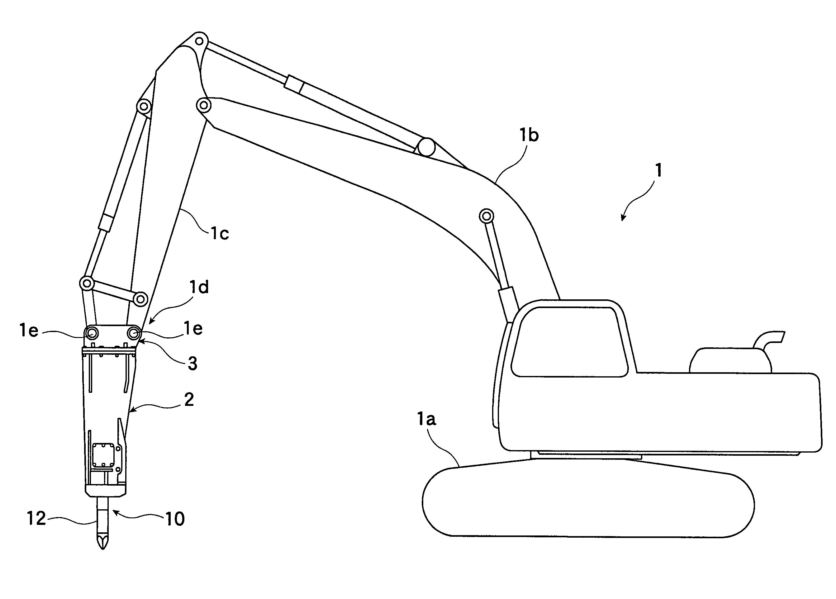
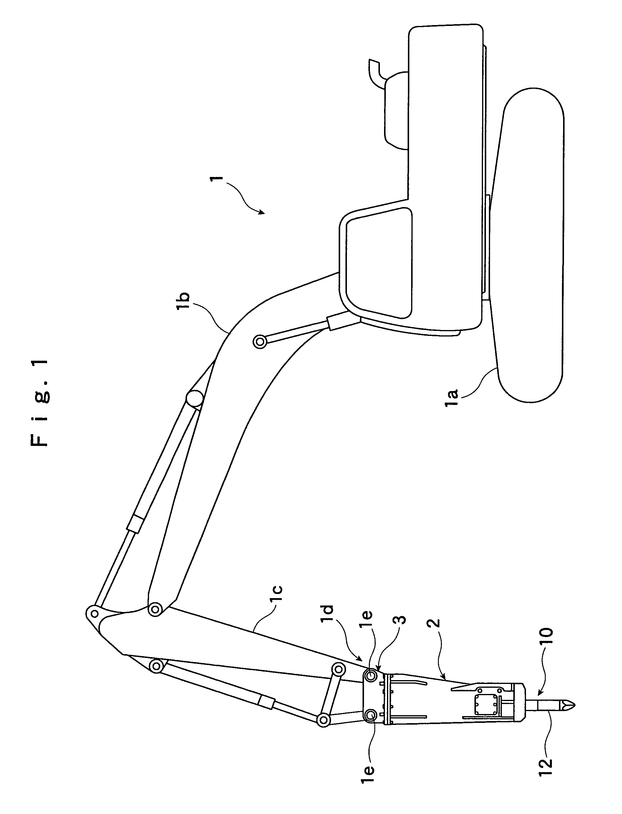
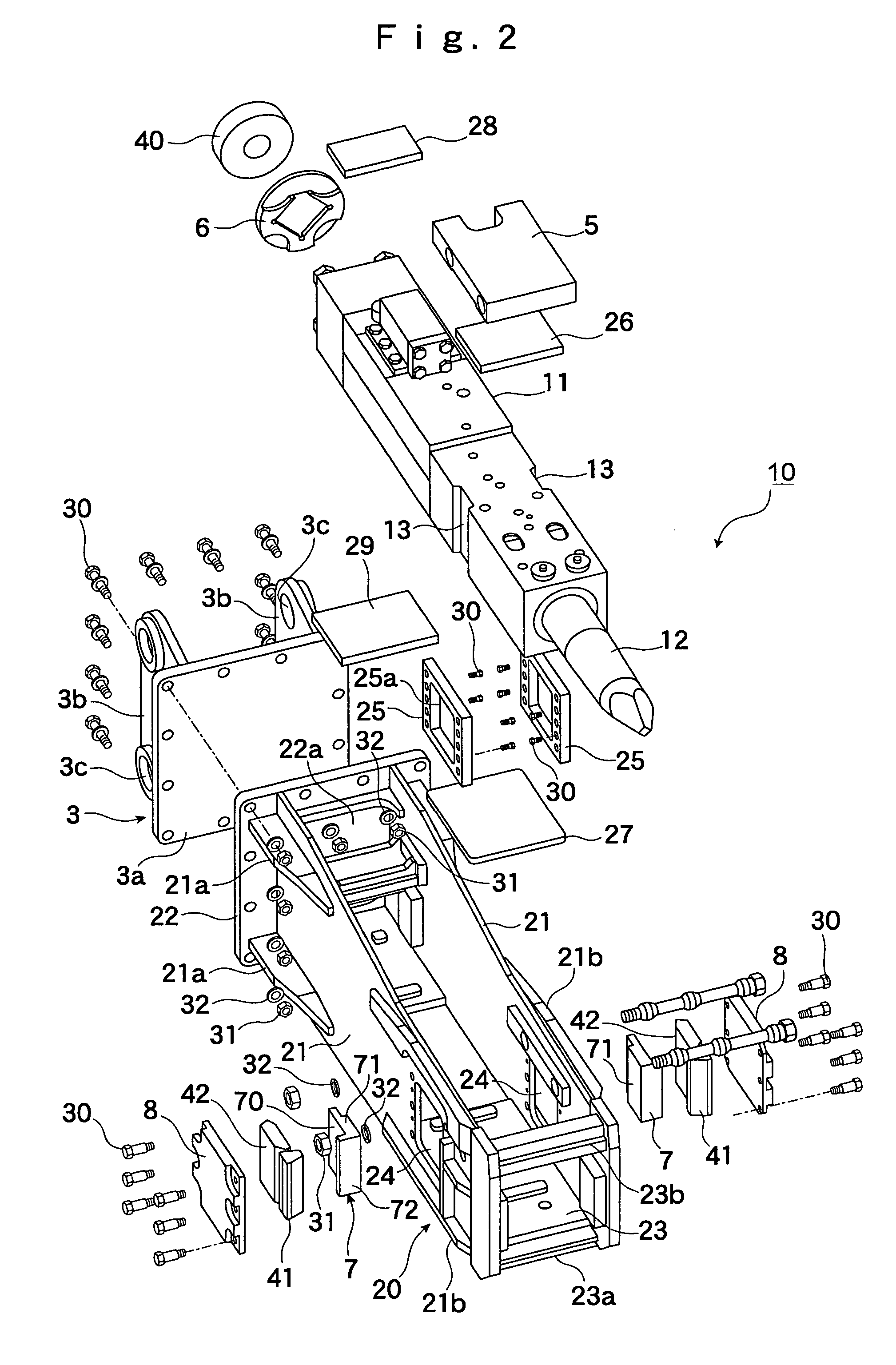
[0044]FIG. 1 is an explanatory view of a working machine which uses a breaker mounting bracket (hereinafter referred to as “bracket”) of embodiment 1, FIG. 2 is an exploded perspective view of the bracket of the embodiment 1, FIG. 3 is a perspective view of the bracket of the embodiment 1, FIG. 4 is a side view of the bracket of the embodiment 1, FIG. 5 is a bottom plan view of the bracket of the embodiment 1, FIG. 6 is a plan view with a part in cross section of the bracket of this embodiment, and FIG. 7 is an enlarged view of an essential part shown in FIG. 6.

[0045]In FIG. 1, numeral 1 indicates the working machine provided with a crawler-type traveling apparatus 1a, wherein an arm 1c is pivotally connected to the boom 1b and a breaker 10 is mounted on a distal end portion of the arm 1c by way of the bracket 2 which constitutes a gist of the embodiment 1. Numeral 1d indi...

embodiment 2

[0065]FIG. 8A, FIG. 8B and FIG. 8C are a plan view, a side view and a front view of a breaker mounting bracket of the embodiment 2 respectively and FIG. 9 is an explanatory view of the support structure of a breaker body. Here, parts having the same functions as corresponding parts in the embodiment 1 are given the same symbols and the explanation thereof is omitted.

[0066]The breaker mounting bracket of the embodiment 2 includes left and right side plates 21 having an approximately rectangular shape which are arranged to face the both side surfaces of the breaker body 11 formed in a longitudinal and approximately rectangular parallelepiped shape and an end plate 22 having an approximately square shape which are arranged on proximal end sides of the side plates 21. Here, as shown in FIG. 9, the breaker mounting bracket includes a pair of left and right resilient bodies (first side-plate side resilient bodies) 101, 102 which are formed on respective inner sides of the left and right s...


PUM

PropertyMeasurementUnit
breaking actionaaaaaaaaaa
resilientaaaaaaaaaa
supporting forceaaaaaaaaaa

Abstract

The present invention provides a breaker mounting bracket a breaker mounting bracket for mounting a breaker body on a distal end of an arm of a working machine or the like. The breaker mounting bracket includes left and right side plates which are arranged to face each other in an opposed manner, an end plate which is provided between proximal end portions of both side plates and forms a connecting portion with a distal end of the arm of the working machine, and resilient bodies which come into contact with and support the breaker body and are mounted on inner sides of the left and right side plates and the end plate.

Description

BACKGROUND OF THE INVENTION[0001]1. Field of the Invention[0002]The present invention relates to a breaker mounting bracket, and more particularly to a bracket which is served for mounting a breaker on a distal end portion of an arm of a power shovel or the like.[0003]2. Explanation of the Related Arts[0004]Conventionally, the mounting of a breaker on a distal end of an arm of a working machine is conducted by way of a bracket.[0005]In performing a crushing operation using the breaker which is hydraulically operated, the vibrations attributed to an impact of the crushing operation are transmitted to the arm and, thereafter, are transmitted to the working machine and hence, it is difficult for an operator to smoothly manipulate the breaker. Accordingly, there has been proposed a technique which mounts a buffer device on a bracket to which the breaker is mounted (see Japanese Patent Laid-open Hei9 (1997)-155766).[0006]The buffer device disclosed in Japanese Patent Laid-open Hei9 (1997...

Claims


Application Information

Patent Timeline
Patent Type & Authority Patents(United States)
IPC IPC(8): B25D17/24
CPCE02F3/966E04G23/082E02F3/36B25B21/02
Inventor YOSHIMURA, TADASHIHARAGUCHI, NAOFUMIJONO, KOZO
Owner TOKU PNEUMATIC TOOL MFG
Learn More