Nail guiding apparatus of nailing machine

a technology of guiding apparatus and nailing machine, which is applied in the direction of nailing tools, manufacturing tools, stapling tools, etc., can solve the problems of unstable operation of positioning nailing machine, increased cost, and large outer shape of nose portion, so as to achieve easy separation and easy to carry out

Active Publication Date: 2009-12-08
MAX CO LTD
View PDF15 Cites 25 Cited by
  • Summary
  • Abstract
  • Description
  • Claims
  • Application Information

AI Technical Summary

Benefits of technology

[0013]According to an embodiment of the invention, a nail guide member for guiding a nail member struck by the driver is provided with a projected portion an outer diameter shape of which is formed in a half cut converging taper shape and which advances into an inside of a nail hole formed at a fixed piece member to position the nailing machine to the nail hole, a guiding guide groove formed to be able to guide a front end of the nail struck by the driver to the projected portion, and a bulged portion formed on an upper side of the projected portion and brought into contact with a surface of the fixed piece member, and the bulged portion constitutes a fulcrum of inclination when the bulged portion is inclined to a front side. As a result, after the projected portion of the nail guide member is advanced into the nail hole of the fixed member to position, when the nailing machine is inclined to the front side, the nailing machine is inclined by constituting the fulcrum by the bulged portion of the nail guide member and therefore, the projected portion of the nail guide member is not moved to an end edge on a rear side of the nail hole. Therefore, a dimension of guiding the front end of the nail guided to the projected portion by the guiding guide groove of the nail guide member to inside of the nail hole can be ensured, and even when the nail is struck out in a state of inclining the nailing machine, a front end of the nail can firmly be guided to inside of the guide hole.
[0014]Further, although there is a case in which when an inner diameter of the nail hole formed at the construction metal piece differs, a depth of advancing the projected portion of the nail guide member formed in the taper shape into the guide hole is changed, as a result, a depth of striking the nail struck out from the nailing machine is varied, since the bulged portion is formed on the upper side of the projected portion in the taper shape, regardless of a size of a dimension of a diameter of the nail hole of the construction metal piece, the bulged portion is engaged with the surface of the construction metal piece, a positional relationship between the nail guide member and the surface of the construction metal piece is maintained constant and therefore, the depth of striking the nail struck out from the nailing machine can be maintained constant.
[0015]Further, according to an embodiment of the invention, the nail guide member is arranged between the side walls opposed to each other provided movably along the nose portion and arranged to be projected from the front end of the injection port such that at least the projected portion and the bulged portion are projected and held between the opposed side walls by the pin member the one end side of which is formed with the locking edge portion and the other end side of which is mounted with the elastic ring-like member. Therefore, by detaching the elastic ring-like member mounted to the end portion of the pin, the nail guide member can easily be separated from the contact member by drawing out the pin, further, the nail guide member can be attached to the contact member by inserting the pin and mounting the elastic ring-like member to an end portion of the pin in the state of arranging the nail guide member between the opposed side walls of the contact member. As a result, the operation of interchanging the nail guide member can easily be carried out without needing any tool.

Problems solved by technology

However, in the former mechanism, the front nail of the connected nails connected by way of a connecting band is projected from the injection port and the tip of the nail is inserted into the hole of the construction metal piece to thereby position the nail machine and therefore, there poses a problem that the front nail is supported by a rigidity of the connecting band of the connected nails and operation of positioning the nail machine becomes unstable.
Further, according to the latter mechanism, the push piston mechanism for moving the nail supplied into the injection port to the direction of the front end of the injection port needs to be installed to the nose portion, cost is increased, further, an outer shape of the nose portion becomes large to hamper operability.
Further, according to the mechanisms, the nailing machine is guided to the nail hole of the construction metal piece by the tip of the nail projected from the injection port of the nose portion and therefore, a safety mechanism for starting the nailing machine by pressing a contact member arranged to be projected frontward from the nose portion to the struck member and by a trigger operated by the hand grabbing a grip cannot be used.
Therefore, there poses a problem of needing a safety apparatus by a complicated mechanism of operating to project a contact member in the direction of the front end along the nose portion by operating the trigger after positioning the tip of the nail projected from the injection port at inside of the nail hole and starting the nailing machine when the contact member impinges on the struck member and cannot be moved to the position projected to the front end side of the nose portion.
When the nail is struck by starting the nailing machine in the inclined state in this way, the tip of the nail guided by the nail guide member 50 impinges on the surface of the construction metal piece M, the nail jumps back in an unexpected direction and therefore, the operation is extremely dangerous.
Further, although since the front end portion 51 of the nail guide member 50 is formed to be thin, the front end portion 51 is easy to be destructed and needs to be interchanged frequently, in interchanging the nail guide member 50, a tool of a spanner, a screwdriver or the like is needed to pose a problem that the nail guide member 50 cannot easily be interchanged at an operation site.

Method used


Image

  • Nail guiding apparatus of nailing machine
  • Nail guiding apparatus of nailing machine
  • Nail guiding apparatus of nailing machine

Examples


Embodiment Construction

[0048]Embodiments of the invention will be explained in reference to the drawings as follows.

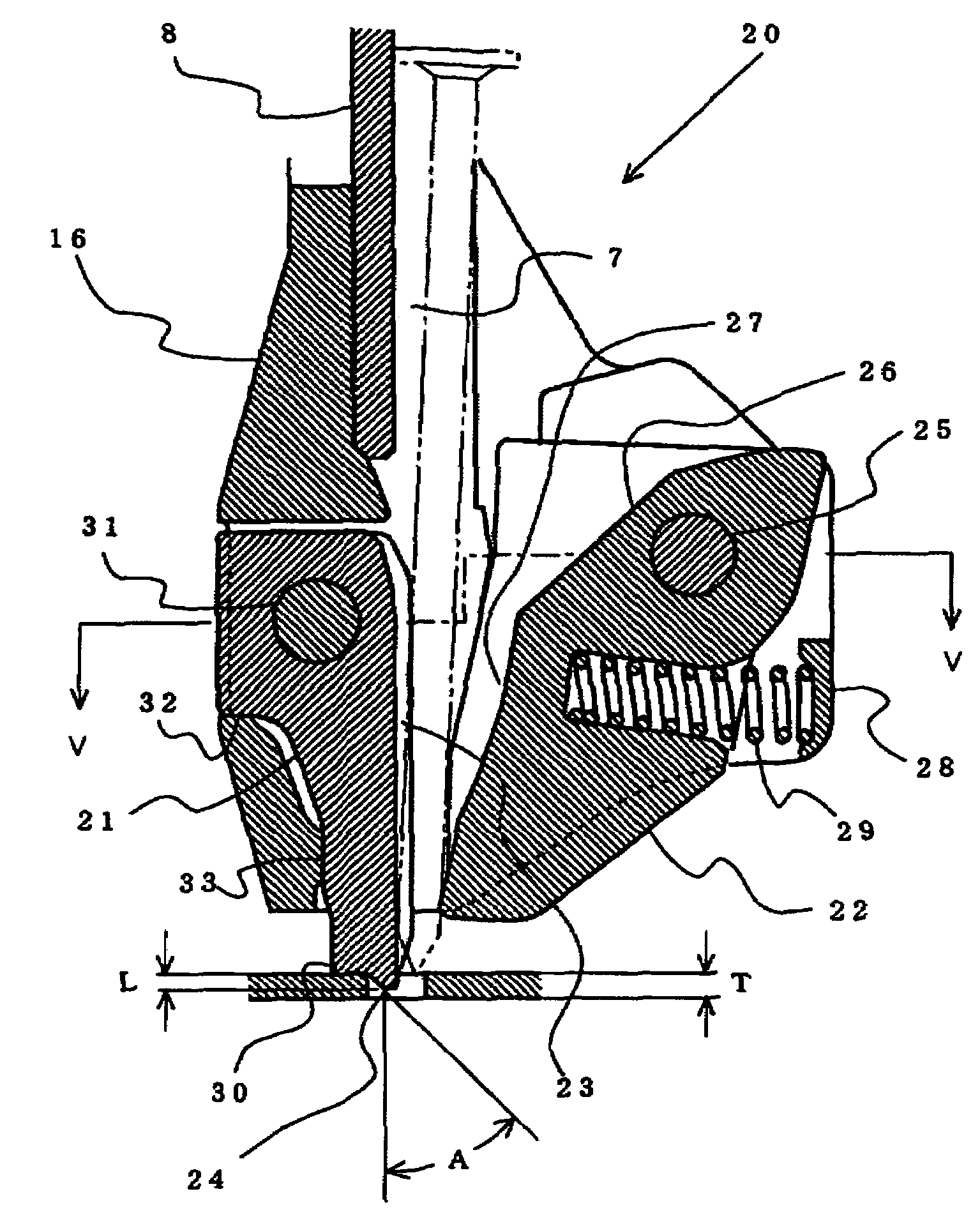
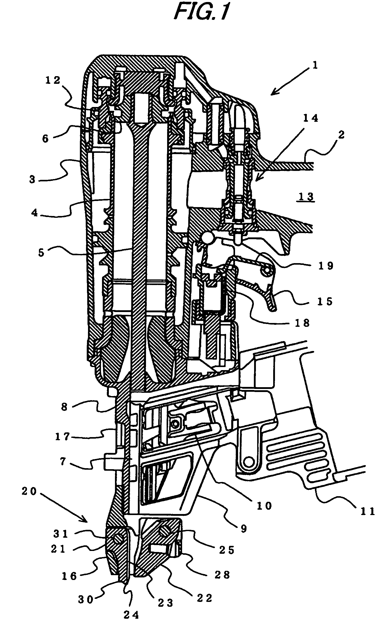
[0049]FIG. 1 shows a nailing machine 1 having a mechanism of guiding a nail according to an embodiment of the invention. A strike cylinder 4 is arranged at inside of a housing 3 in a hollow shape integrally formed with a grip portion 2. Inside of the strike cylinder 4 is slidably contained with a strike piston 6 coupled with a driver 5 for striking a nail at a lower face thereof. A lower side of the housing 3 is attached with a nose portion 8 forming an injection port 7 for striking and guiding a nail to a struck member. The driver 5 is slidably guided at inside of the injection port 7 of the nose portion 8. A rear side of the injection port 7 of the nose portion 8 is formed with an opening for introducing a nail to inside of the injection port 7. A nail supply guide 9 is formed between one side edge of the opening and a magazine 11 containing connected nails shaft portions of which are conn...


PUM

PropertyMeasurementUnit
angleaaaaaaaaaa
lengthaaaaaaaaaa
lengthaaaaaaaaaa

Abstract

A nailing machine for striking a nail supplied into an injection port formed at a nose portion by a driver to strike out from inside of the injection port is provided with a nail guide member on a front side of the injection port. The nail guide member is provided with a guiding guide groove for guiding a front end portion of the nail struck out from inside of the injection port at an inner side face thereof, provided with a projected portion an outer diameter shape of which is formed in a half cut converging taper shape, and provided with a bulged portion brought into contact with a surface of a construction metal piece on an upper side of the projected portion. The nailing machine is positioned by inserting the projected portion into a nail hole formed at a construction metal piece. The bulged portion constitutes a fulcrum of rotation by which the nailing machine is inclined when the nailing machine is inclined to a front side.

Description

TECHNICAL FIELD[0001]The present invention relates to a nail guiding apparatus of a nailing machine to fasten a construction metal piece or the like by guiding a fastening piece of a nail or the like into a nail hole previously formed at a fixed member of the construction metal piece or the like by striking out the nail supplied into an injection port formed at a nose portion from the injection port by way of a driver impactively driven by power of compressed air or the like.BACKGROUND ART[0002]In wooden construction, a construction metal piece previously formed with a number of nail holes is frequently used in connecting a column member, a beam member and a girder member or the like, or for reinforcing connecting portions of the structure members. The construction metal pieces are struck to fasten to a structure member of a column or the like by nails. In striking to fasten such a construction metal piece previously formed the nail hole, a nailing machine made to continuously strik...

Claims


Application Information

Patent Timeline
Patent Type & Authority Patents(United States)
IPC IPC(8): B25C7/00B25C1/00B25C1/04
CPCB25C1/008B25C7/00B25C1/041
Inventor YAMAMOTO, HIROKIADACHI, MICHIAKIOGAWA, TATSUSHI
Owner MAX CO LTD
Why Eureka
Try Eureka