
Liquid ejection apparatus, liquid ejection method and image forming apparatus

a liquid ejection and liquid ejection technology, applied in printing and other directions, can solve the problems of reducing image quality, increasing the liquid inside the nozzle, and difficult to apply compositions, and achieves high viscosity

Inactive Publication Date: 2009-12-08
FUJIFILM CORP
View PDF3 Cites 3 Cited by
  • Summary
  • Abstract
  • Description
  • Claims
  • Application Information

AI Technical Summary

Benefits of technology

[0009]The present invention has been contrived in view of these circumstances, an object thereof being to provide a liquid ejection apparatus, a liquid ejection method and an image forming apparatus whereby liquid of high viscosity can be ejected without giving rise to satellite droplets.
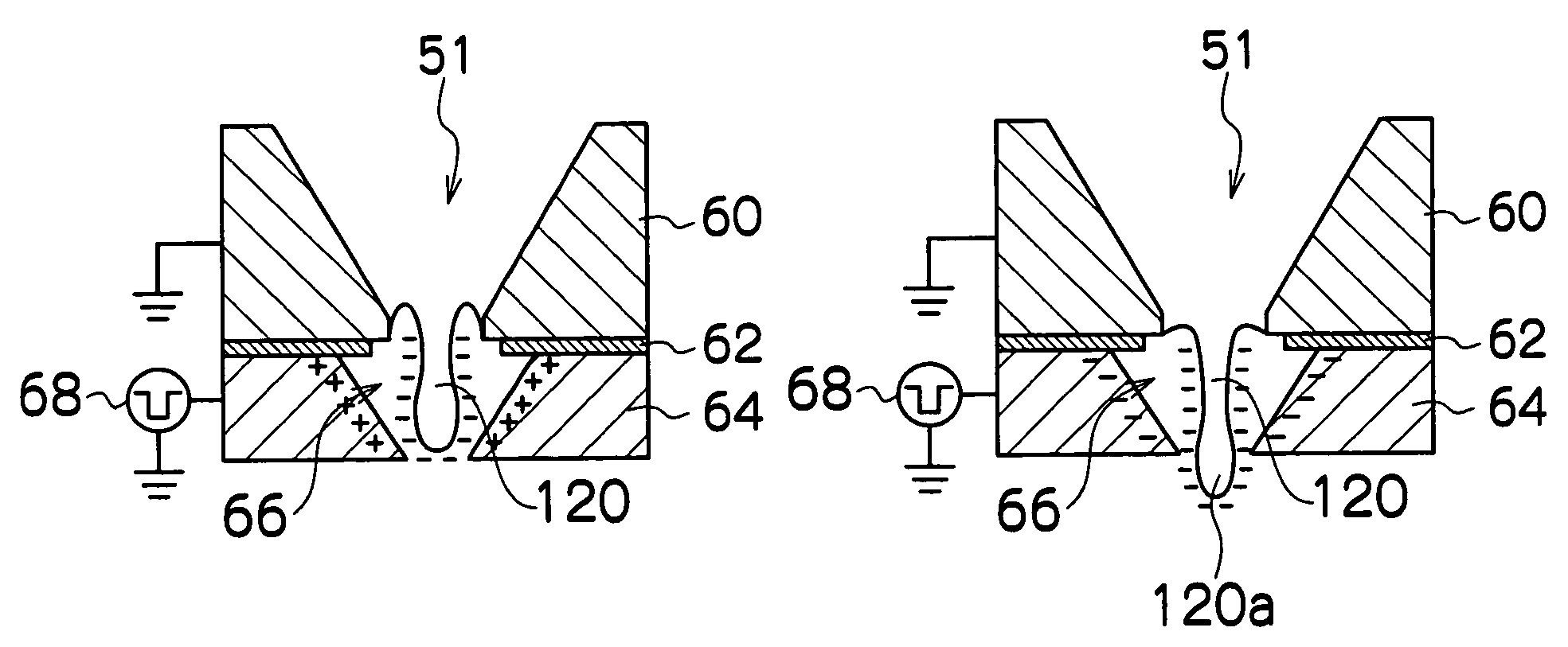
[0011]According to this aspect of the present invention, during the liquid ejection, the electric charge is induced in the surface of the liquid column formed to the long and thin column shape extending in the ejection direction from the nozzle, by means of the electric field generated by the electrode, and by reversing the polarity of the electrode when the liquid column has grown to the prescribed length, the liquid surface and the electrode assume the same polarity, and severing force acts in the contrary directions on the front end portion and the rest of the liquid column, whereby the front end portion of the liquid column can be severed. By separating the main droplet corresponding to the front end portion of the liquid column by cutting off the liquid ligament by means of the electrostatic field, it is possible to eject the droplet of ink of high viscosity without giving rise to satellite droplets, regardless of the surface tension of the ink or the ejection speed.
[0013]According to this aspect of the present invention, the taper-shaped hole sections that become gradually narrower along the ejection direction are formed in the electrode, in positions corresponding to the nozzles. Hence, the front end portion of the liquid column can be severed efficiently.
[0016]According to the present invention, during liquid ejection, electric charge is induced in a surface of a liquid column formed to a long and thin column shape extending in an ejection direction from a nozzle, by means of an electric field generated by an electrode, and by reversing the polarity of the electrode when the liquid column has grown to a prescribed length, the liquid surface and the electrode assume the same polarity, and severing force acts in the contrary directions on a front end portion and the rest of the liquid column, whereby the front end portion of the liquid column can be severed. By separating the main droplet corresponding to the front end portion of the liquid column by cutting off the liquid ligament by means of the electrostatic field, it is possible to eject the droplet of ink of high viscosity without giving rise to satellite droplets, regardless of the surface tension of the ink or the ejection speed.

Problems solved by technology

This can give rise to minute ink droplets referred to as “satellite droplets” accompanying the main ink droplet, which degrade the image quality.
Moreover, in practical terms, if the surface tension is excessively raised, then the actuator power required to break the free surface (also referred to as the “meniscus”) of the liquid inside the nozzle increases, and further problems occur in relation to the permeability of the liquid into the recording medium after landing of the liquid droplets on the recording medium.
Japanese Patent Application Publication No. 2004-066531 assumes the use of a recording apparatus of a continuous inkjet (CIJ) type, and supposes that the free surface of the ink is formed into the thread shape; however, in a recording apparatus of a drop on demand (DOD) type, which is typical in a piezoelectric system, the principal focus is on preventing the occurrence of satellite droplets by restricting elongation of the liquid column, and it is difficult to apply the composition described in Japanese Patent Application Publication No. 2004-066531 to the recording head that uses the piezoelectric method.
This is because in the piezoelectric type of recording head, in order to prevent satellite droplets, it is necessary to suppress the thread shape (the trail of the liquid column), as much as possible, but if the electrode composition according to Japanese Patent Application Publication No. 2004-066531 is combined with the piezoelectric type of recording head, then the pulling electrode in the vicinity of the target continues to pull on the liquid column and it is impossible to avoid elongation of the liquid column.
In particular, in a multi-nozzle composition, there are concerns regarding the effects of electric field cross-talk between the nozzles.
Furthermore, if high voltages are applied to the respective electrodes, then there is a risk of electrical breakdown between the electrodes.

Method used


Image

  • Liquid ejection apparatus, liquid ejection method and image forming apparatus
  • Liquid ejection apparatus, liquid ejection method and image forming apparatus
  • Liquid ejection apparatus, liquid ejection method and image forming apparatus

Examples


Embodiment Construction

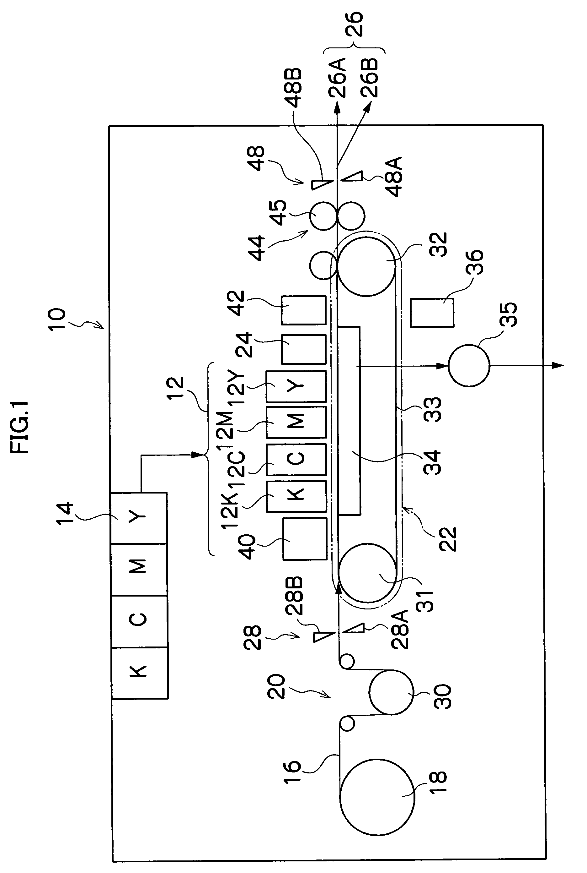
[0025]FIG. 1 is a general schematic drawing of an inkjet recording apparatus which is an image recording apparatus according to an embodiment of the present invention. As shown in FIG. 1, the inkjet recording apparatus 10 includes: a printing unit 12 having a plurality of recording heads 12K, 12C, 12M, and 12Y for ink colors of black (K), cyan (C), magenta (M), and yellow (Y), respectively; an ink storing and loading unit 14, which stores inks of K, C, M and Y to be supplied to the recording heads 12K, 12C, 12M, and 12Y; a paper supply unit 18, which supplies recording paper 16; a decurling unit 20, which removes curl in the recording paper 16; a suction belt conveyance unit 22, which is disposed facing the nozzle face (ink-droplet ejection face) of the print unit 12 and conveys the recording paper 16 while keeping the recording paper 16 flat; a print determination unit 24, which reads the printed result produced by the printing unit 12; and a paper output unit 26, which outputs ima...


PUM


Abstract

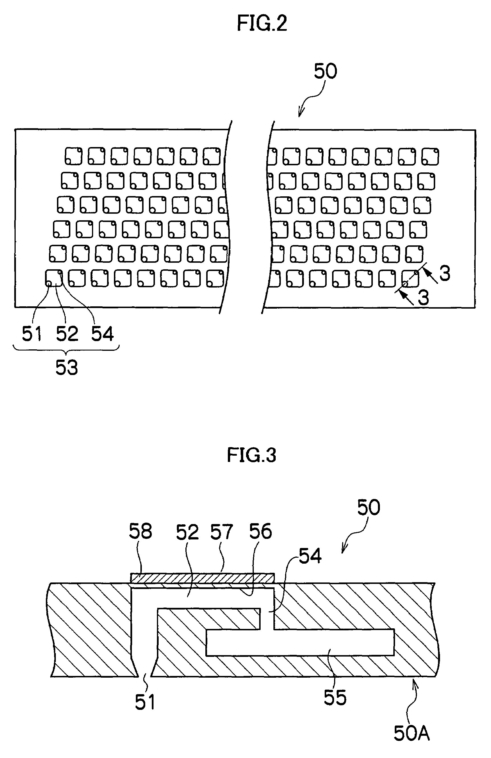
The liquid ejection apparatus includes: a pressure chamber which contains liquid; a nozzle which is connected to the pressure chamber, the liquid being ejected in an ejection direction through the nozzle; a piezoelectric element which applies pressure change to the liquid in the pressure chamber, a part of the liquid protruding from the nozzle upon the pressure change and growing into a column of the liquid having a longitudinal direction parallel with the ejection direction; an electrode which induces a charge on a surface of the column of the liquid; and a voltage control device which controls voltage applied to the electrode, the voltage control device reversing polarity of the electrode when the column of the liquid has grown to a prescribed length.

Description

BACKGROUND OF THE INVENTION[0001]1. Field of the Invention[0002]The present invention relates to a liquid ejection apparatus, a liquid ejection method and an image forming apparatus, and more particularly, to a liquid ejection apparatus which ejects liquid through nozzles connected to pressure chambers by applying pressure change to the liquid inside the pressure chambers by using the displacement of piezoelectric elements.[0003]2. Description of the Related Art[0004]There is known a recording head used in an inkjet recording apparatus that ejects droplets of ink through nozzles connected to pressure chambers by applying pressure change to the ink inside the pressure chambers by using the displacement of piezoelectric elements. In a recording head based on this piezoelectric method, and in particular when using an ink of high viscosity, a phenomenon referred to as “trailing” is liable to occur in which the ink droplet ejected from a nozzle forms a column shape and trails during its ...

Claims


Application Information

Patent Timeline
Patent Type & Authority Patents(United States)
IPC IPC(8): B41J2/045
CPCB41J2/06
Inventor ONOZAWA, SHO
Owner FUJIFILM CORP
Learn More