Balloon catheter with improved resistance to non-deflation

a balloon catheter and non-deflation technology, applied in the field of balloon catheters, can solve the problems of difficult or impossible fluid withdrawal, the wall of the lumen, etc., and achieve the effect of increasing the stiffness of the material, deflating the balloon, and increasing the resistance to non-deflation

Active Publication Date: 2009-12-08
CR BARD INC
View PDF20 Cites 30 Cited by
  • Summary
  • Abstract
  • Description
  • Claims
  • Application Information

AI Technical Summary

Benefits of technology

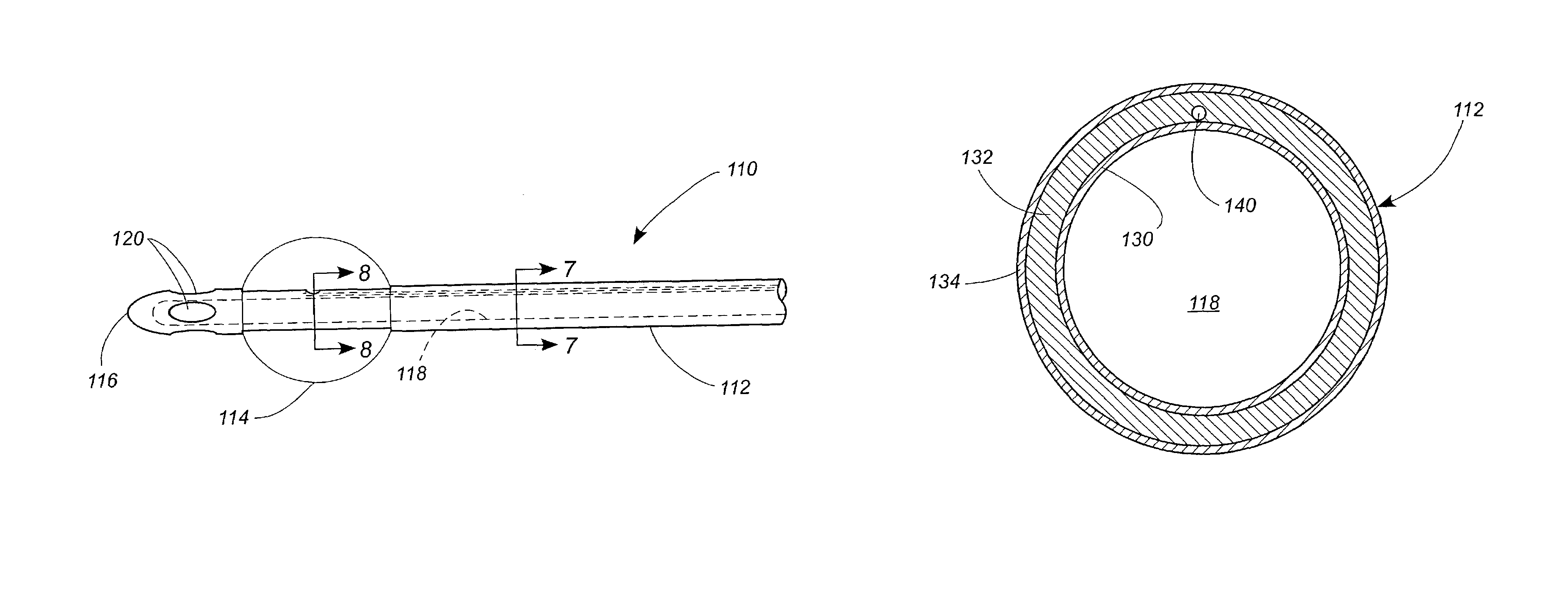
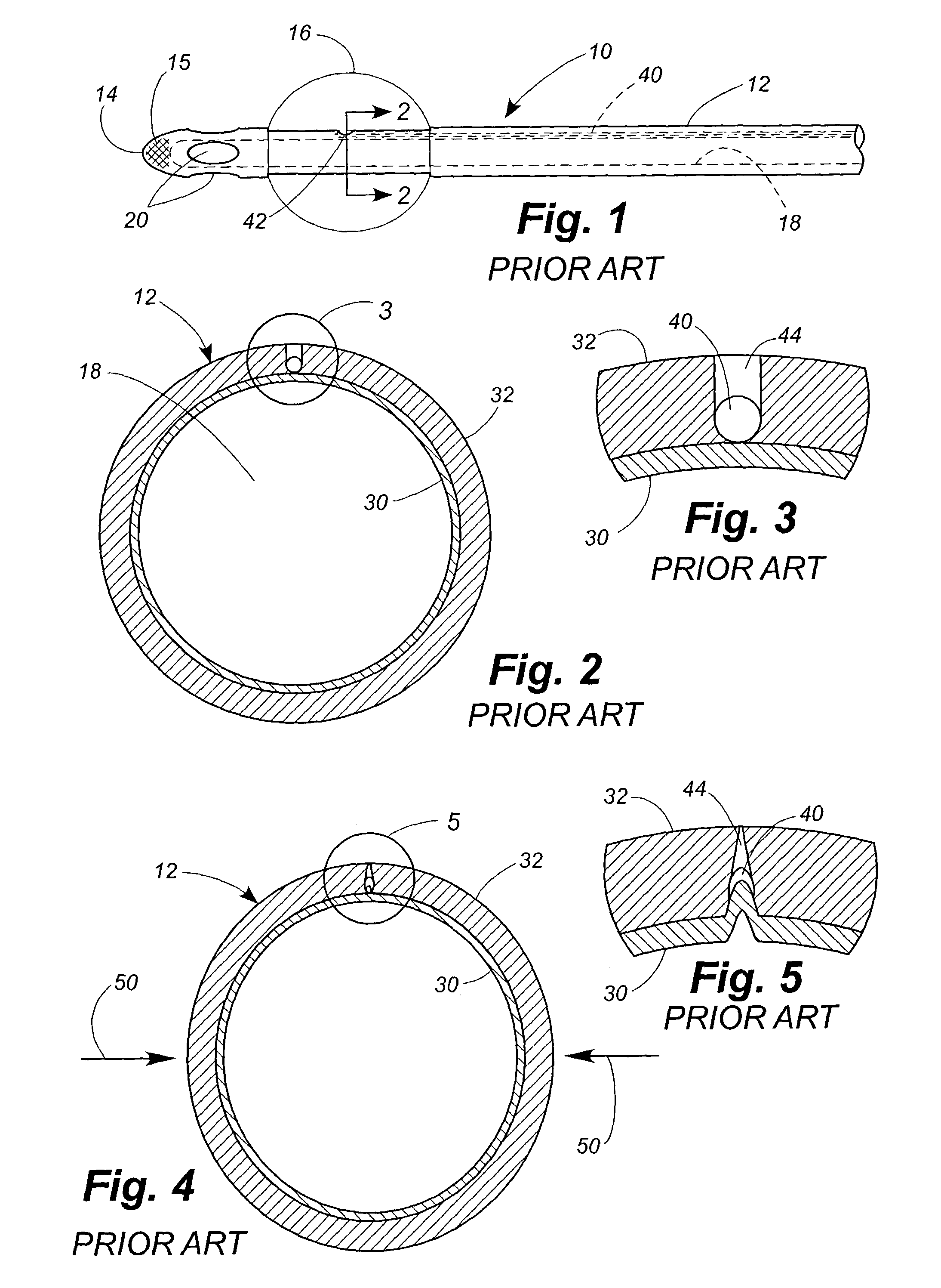
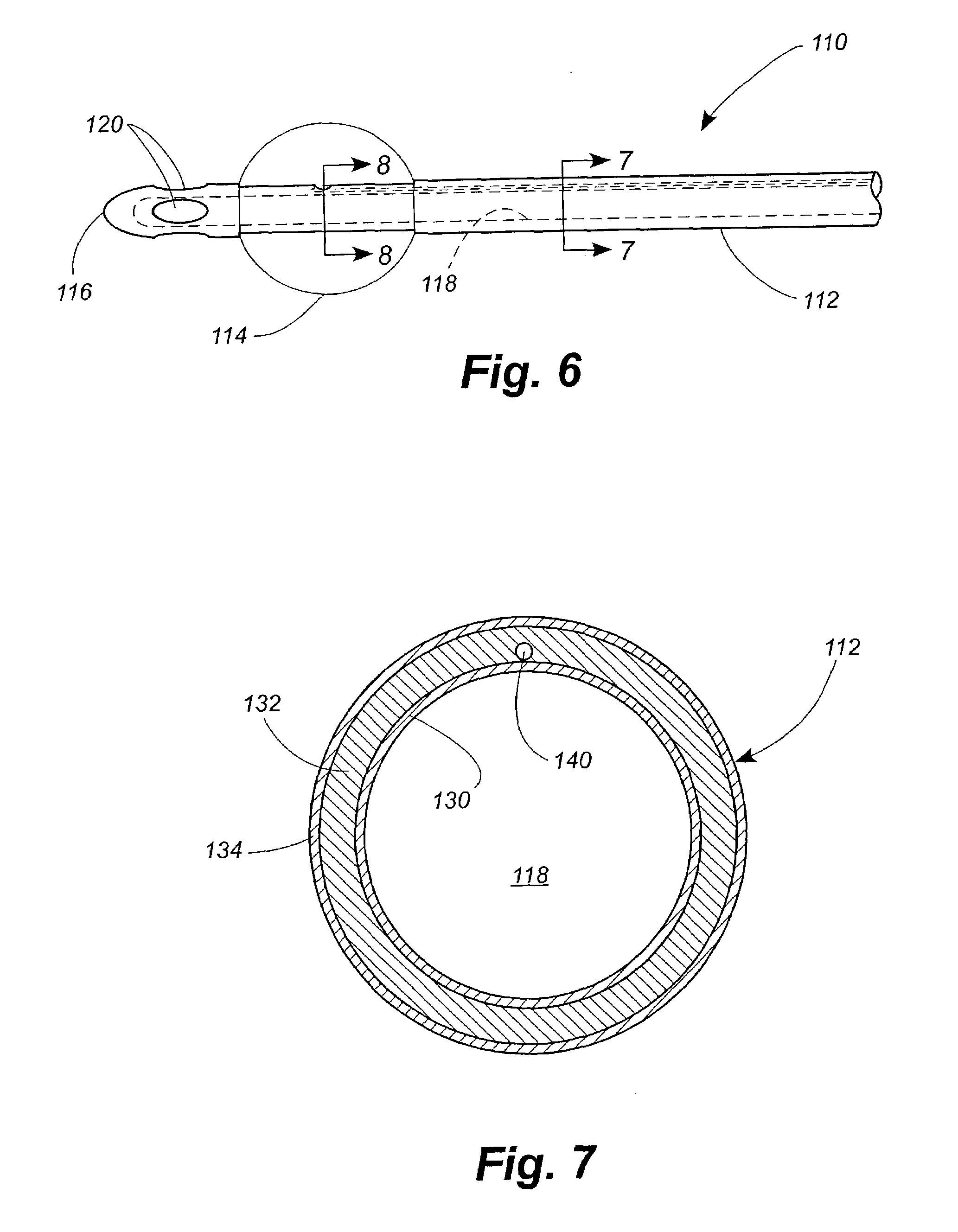
[0007]Stated generally, the present invention comprises a balloon catheter with enhanced resistance to non-deflation. The invention is based on the discovery that most non-deflating balloons are the consequence of the inflation lumen collapsing under radial pressure exerted against the balloon and hence against the underlying catheter shaft. In addition, the negative pressure exerted within the inflation lumen by the syringe trying to withdraw fluid from the balloon will further collapse the walls of the lumen, making fluid withdrawal difficult or impossible. This invention is further based on the discovery that by increasing the stiffness of the material making up the innermost portion of the wall of the catheter shaft, the patency of the inflation lumen can be maintained, making it possible to deflate the balloon under a wider range of circumstances. Surprising, these results occur even though the stiffened material is located interior to the inflation lumen (i.e. closer to the center of the catheter diameter than the inflation lumen) rather than surrounding or exterior to the inflation lumen. It has further been found that increasing the stiffness of only the innermost material achieves these desirable results without the undesirable consequences of significantly increasing the stiffness of the catheter.

Problems solved by technology

In addition, the negative pressure exerted within the inflation lumen by the syringe trying to withdraw fluid from the balloon will further collapse the walls of the lumen, making fluid withdrawal difficult or impossible.

Method used


Image

  • Balloon catheter with improved resistance to non-deflation
  • Balloon catheter with improved resistance to non-deflation
  • Balloon catheter with improved resistance to non-deflation

Examples


example 1

[0051]Example 1 Catheters were prepared using the same procedures as those used for the Comparative Example 1 catheters except that the latex material used in the rubberize layer had a dry Young's Modulus of approximately 120 psi and a wet Young's Modulus of approximately 85 psi. The increase in Young's Modulus was accomplished by the addition of MacNamee Clay and Barium Sulfate to the rubberize latex material during formulation. Furthermore, the Example 1 Catheters were prepared without incorporating the reinforcement cap into the catheter tip.

example 2

[0060]COMPARATIVE EXAMPLE 4 was repeated, except that the latex catheter was prepared using materials having the same Young's Modulus values as the materials used in EXAMPLE 1. The patency of the inflation lumen was essentially retained at chamber pressures as high as 40 pounds per square inch, gage (psig).

example 3

[0061]The procedures of COMPARATIVE EXAMPLE 4 are repeated, except that the build up layer, not the rubberize layer, is prepared using materials having the same Young's Modulus values as the materials used on the rubberize layer in EXAMPLE 1. The rubberize layer has the Young's Modulus values of the rubberize layer in COMPARATIVE EXAMPLE 1. The drainage lumen of the resulting catheter does not retain its patency at elevated air pressures as well as the catheters of EXAMPLE 2.


PUM

PropertyMeasurementUnit
wet Young's Modulusaaaaaaaaaa

Abstract

Balloon catheters are disclosed that comprise a material that confers improved resistance to non-deflation. Balloon catheters are also disclosed that comprise a reduced drainage lumen diameter. In some embodiments the catheters achieve these characteristics without rendering the catheters undesirably stiff.

Description

TECHNICAL FIELD[0001]The present invention relates generally to balloon catheters and relates more specifically to a balloon catheter that exhibits improved resistance to non-deflation.BACKGROUND OF THE INVENTION[0002]Balloon catheters are well known medical devices in which an inflatable member is located adjacent to the distal end of the catheter shaft and inflated once the catheter is positioned within the body of the patient to anchor the distal end. Such catheters comprise an elongated shaft defining a drainage lumen and an inflation lumen. The drainage lumen comprises a major portion of the cross-section of the catheter shaft and is closed at its distal end by a tip portion. Openings or ports distal to the balloon permit fluid to enter the drainage lumen. The proximal end of the drainage lumen is placed in fluid communication with a method of drainage such as a urinary drainage bag. In some embodiments, the communication is made through a drainage funnel located at the proxima...

Claims


Application Information

Patent Timeline
Patent Type & Authority Patents(United States)
IPC IPC(8): A61M27/00A61M25/00A61F2/958
CPCA61M25/0017A61M25/0045A61M25/1027A61M2210/1085A61M25/1029A61M25/10
Inventor DIAZ, JOSEPH ROBERTCAPSTICK, IAN
Owner CR BARD INC
Why Eureka
Try Eureka