Method and apparatus for operating electrical machines

a technology of electrical machines and methods, applied in the direction of machines/engines, electric generator control, dynamo-electric converter control, etc., can solve the problems of affecting power converters and generators are susceptible to grid voltage fluctuations, and voltage fluctuations may be deleterious to the continuous operation of wind turbine generators

Active Publication Date: 2009-12-08
GENERAL ELECTRIC CO +1
View PDF10 Cites 65 Cited by
  • Summary
  • Abstract
  • Description
  • Claims
  • Application Information

AI Technical Summary

Benefits of technology

[0005]In another aspect, a control system for an electrical machine is provided. The electrical machine is configured to be electrically coupled to an electric power system. The electric power system is configured to transmit at least one phase of electric power to and from the electrical machine. The control system facilitates the electrical machine remaining electrically connected to the electric power system during and subsequent to at least one voltage amplitude of the electric power operating outside of a predetermined range for an undetermined period of time.
[0006]In a further aspect, a wind turbine is provided. The wind turbine includes at least one electric power generator configured to be electrically coupled to an electric power system. The electric power system is configured to transmit at least one phase of electric power to and from the generator. The wind turbine also includes at least one control system configured to be electrically coupled to the electric power system. The control system facilitates the electrical machine remaining electrically connected to the electric power system during and subsequent to at least one voltage amplitude of the electric power operating outside of a predetermined range for an undetermined period of time.

Problems solved by technology

Generally, the power converters and the generator are susceptible to grid voltage fluctuations.
Therefore, such grid voltage fluctuations may be deleterious to continuous operation of the wind turbine generator.

Method used


Image

  • Method and apparatus for operating electrical machines
  • Method and apparatus for operating electrical machines
  • Method and apparatus for operating electrical machines

Examples


Embodiment Construction

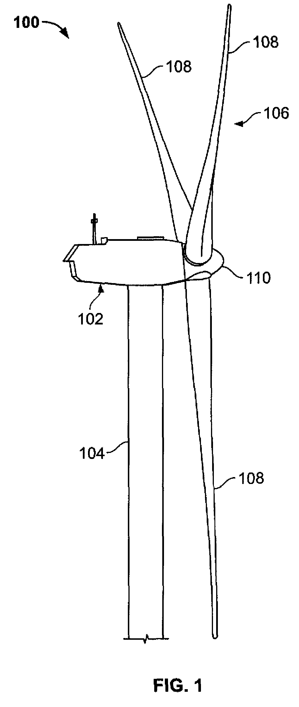
[0013]FIG. 1 is a schematic view of an exemplary wind turbine generator 100. The wind turbine 100 includes a nacelle 102 housing a generator (not shown in FIG. 1). Nacelle 102 is mounted on a tower 104 (a portion of tower 104 being shown in FIG. 1). Tower 104 may be any height that facilitates operation of wind turbine 100 as described herein. Wind turbine 100 also includes a rotor 106 that includes three rotor blades 108 attached to a rotating hub 110. Alternatively, wind turbine 100 includes any number of blades 108 that facilitate operation of wind turbine 100 as described herein. In the exemplary embodiment, wind turbine 100 wind turbine 100 includes a gearbox (not shown in FIG. 1) rotatingly coupled to rotor 106 and a generator (not shown in FIG. 1).

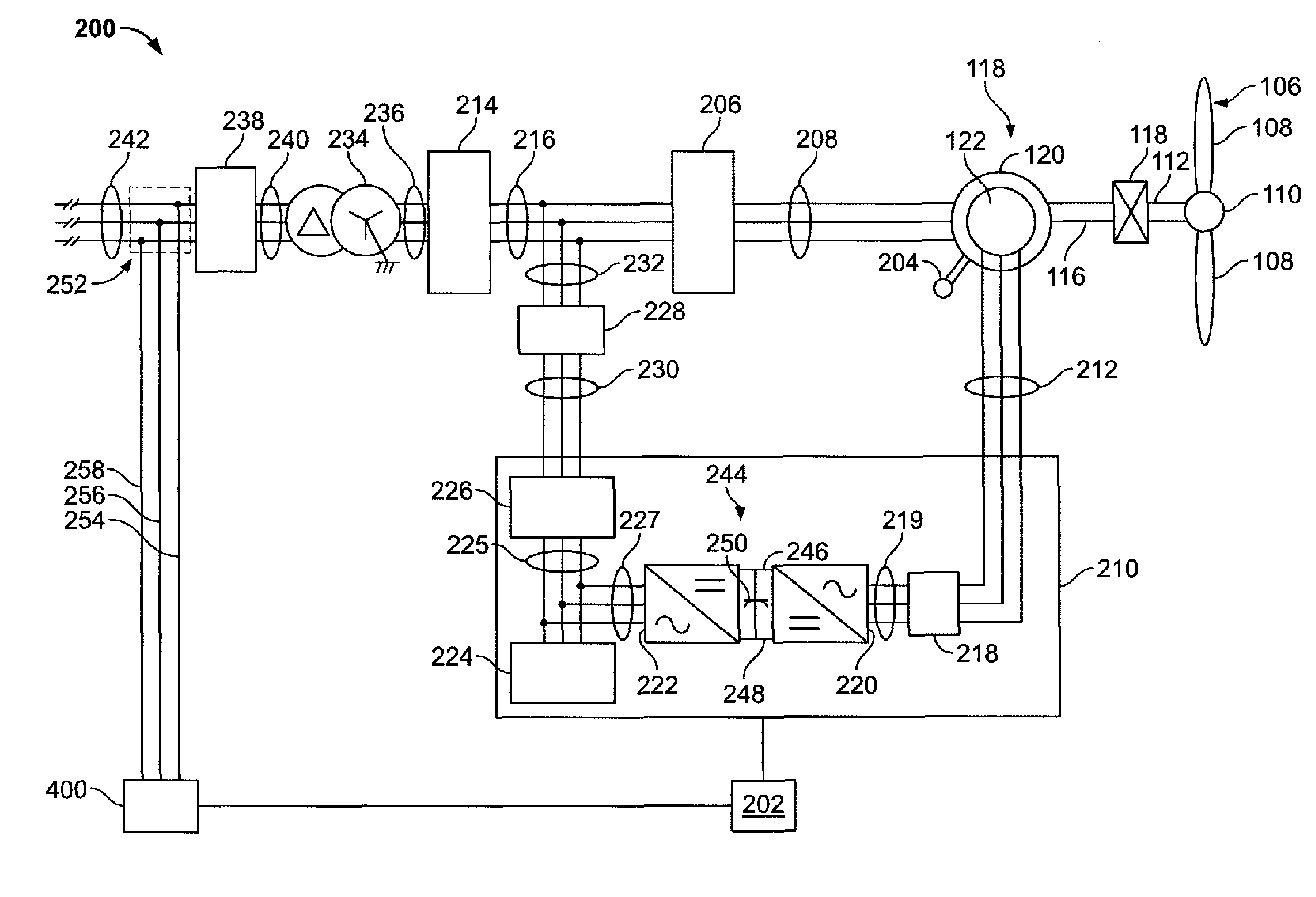
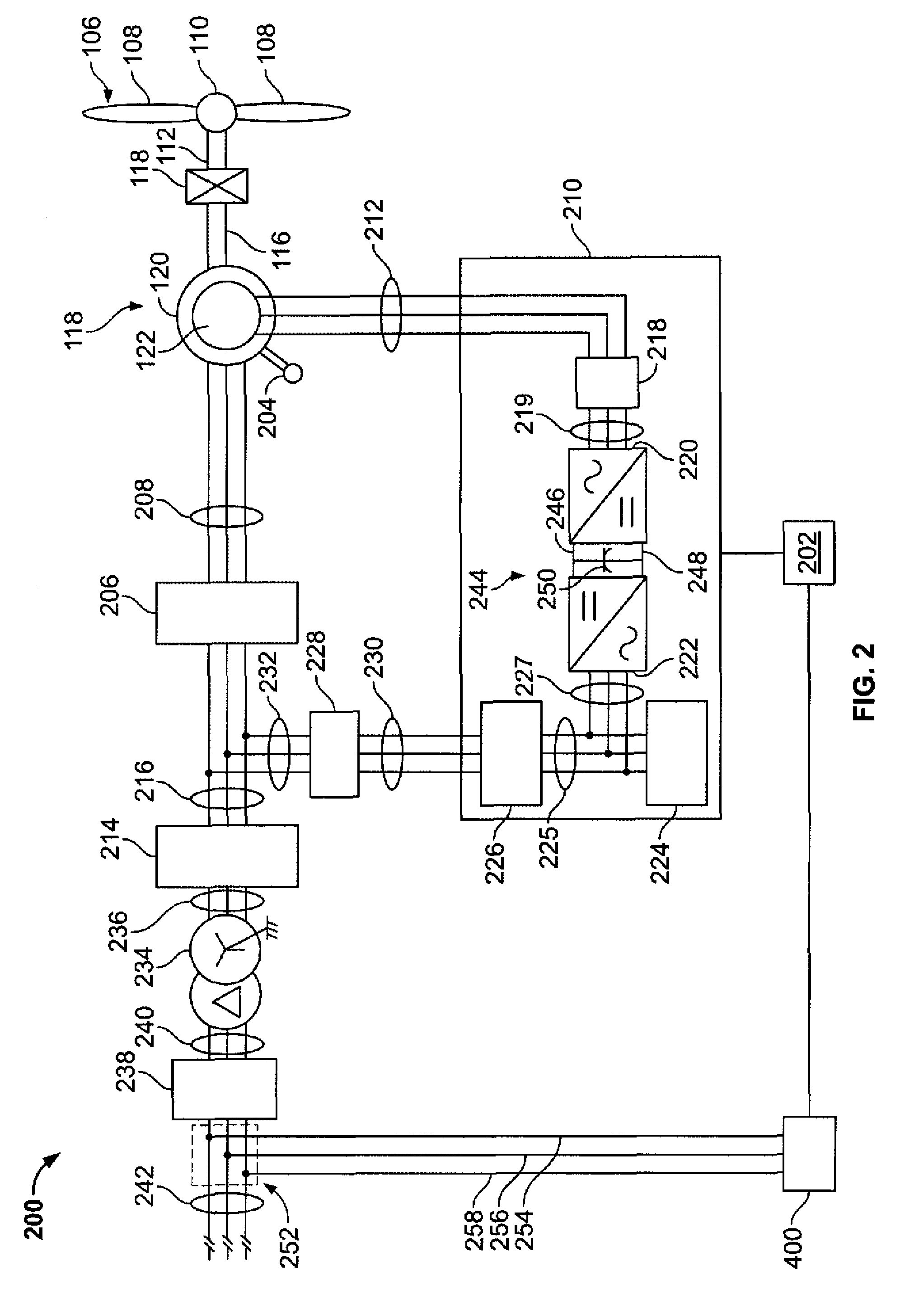
[0014]FIG. 2 is a schematic view of an exemplary electrical and control system 200 that may be used with wind turbine generator 100 (shown in FIG. 1). Rotor 106 includes plurality of rotor blades 108 coupled to rotating hub 110. Rot...


PUM


Abstract

A method for operating an electrical machine includes coupling the electrical machine to an electric power system such that the electric power system is configured to transmit at least one phase of electric power to and from the electrical machine. The method also includes configuring the electrical machine such that the electrical machine remains electrically connected to the electric power system during and subsequent to a voltage amplitude of the electric power system operating outside of a predetermined range for an undetermined period of time.

Description

BACKGROUND OF THE INVENTION[0001]This invention relates generally to electrical machines and more particularly, to methods and apparatus for operating electrical machines.[0002]Generally, a wind turbine generator includes a turbine that has a rotor that includes a rotatable hub assembly having multiple blades. The blades transform mechanical wind energy into a mechanical rotational torque that drives one or more generators via the rotor. The generators are generally, but not always, rotationally coupled to the rotor through a gearbox. The gearbox steps up the inherently low rotational speed of the rotor for the generator to efficiently convert the rotational mechanical energy to electrical energy, which is fed into a utility grid via at least one electrical connection. Gearless direct drive wind turbine generators also exist. The rotor, generator, gearbox and other components are typically mounted within a housing, or nacelle, that is positioned on top of a base that may be a truss ...

Claims


Application Information

Patent Timeline
Patent Type & Authority Patents(United States)
IPC IPC(8): H02P11/00H02P9/00H02P9/04
CPCH02P9/007H02J3/386H02P2101/15H02P9/102F03D7/0284F05B2270/10711H02J2300/28H02J3/381H02J3/44Y02E10/76
Inventor BARKER, SIDNEY A.KLODOWSKI, ANTHONYD'ATRE, JOHNLARSEN, EINARDROBNJAK, GORAN
Owner GENERAL ELECTRIC CO
Why Eureka
Try Eureka