
Location signaling for large-scale, end-to-end, quality-of-service monitoring of mobile telecommunication networks

a technology of quality-of-service monitoring and location signaling, which is applied in the field of mobile telecommunication networks, can solve the problems of difficult model and analysis, complicated queuing phenomena, and disadvantages of both solutions, and achieve the effect of cost-effective collection and further reducing the number of needed measurement points

Active Publication Date: 2009-12-08
TELEFON AB LM ERICSSON (PUBL)
View PDF6 Cites 0 Cited by
  • Summary
  • Abstract
  • Description
  • Claims
  • Application Information

AI Technical Summary

Benefits of technology

This approach reduces the number of measurement points needed, allows for efficient collection of cell-level location information, and ensures network security by using passive monitoring with standardized interfaces, facilitating reliable and cost-effective end-to-end quality-of-service monitoring in UMTS networks.

Problems solved by technology

Furthermore, the use of shared resources leads to rather complicated queuing phenomena, which are difficult to model and analyze.
Both solutions, however, have disadvantages.
Since reliable statistical analysis of a network requires a large amount of network-wide data, the first solution would be rather complicated.
The second solution suffers from the disadvantage that users are identified in RRC cell-update signaling by temporary IDs (i.e., cell radio network temporary identity (RNTI) and UTRAN RNTI).
The time-varying nature of these IDs makes it difficult to associate the transactions measured at higher aggregation points with a mobility pattern tracked in an RRC trace.
Therefore, a measurement system that can be used in any type of UTRAN cannot be based on extracting information from the RNC.
Yet another drawback is that, in order to ensure network security, safe operation of network nodes, and the like, operators typically do not allow for measuring teams (which may be external) to access important network nodes such as the RNC.

Method used


Image

  • Location signaling for large-scale, end-to-end, quality-of-service monitoring of mobile telecommunication networks
  • Location signaling for large-scale, end-to-end, quality-of-service monitoring of mobile telecommunication networks
  • Location signaling for large-scale, end-to-end, quality-of-service monitoring of mobile telecommunication networks

Examples


Embodiment Construction

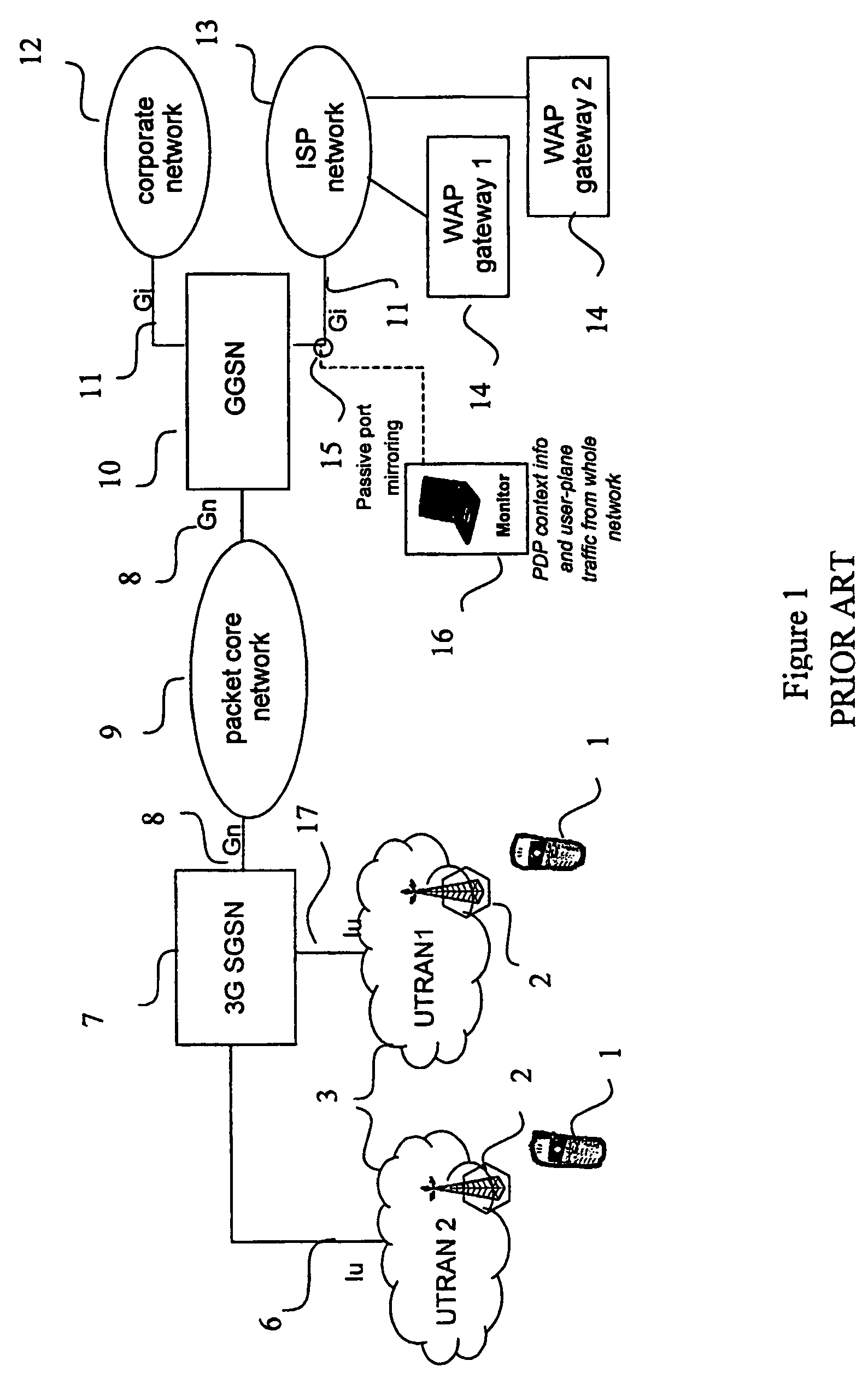
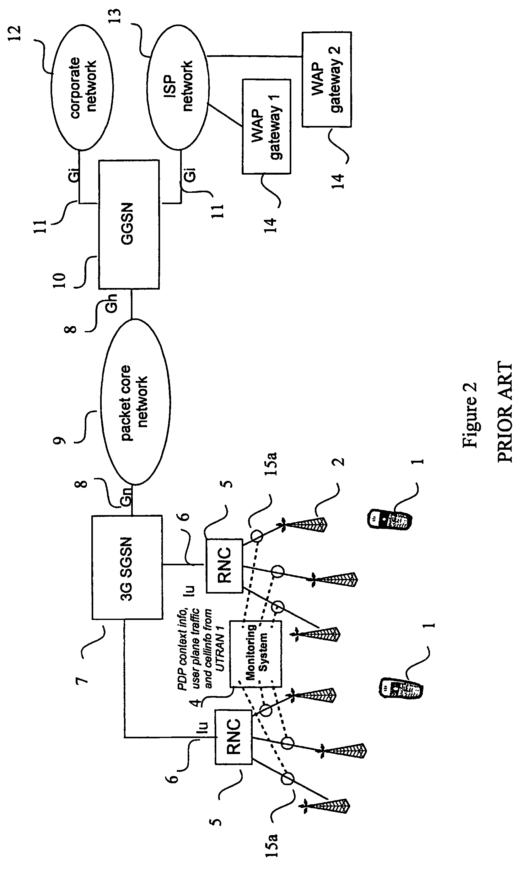
[0034]In FIG. 1, an exemplary telecommunication network is shown according to the location unaware prior art solution, where mobile stations 1 communicate with base stations 2 through radio channels. The base stations are grouped to Radio Network Controllers 5, which are connected to a 3G SGSN 7 through Iu interfaces 6. The 3G SGSN is linked to a packet core network 9 and to a GGSN 10 through Gn interfaces 8. The GGSN is linked to a corporate network 12 and to an ISP network 13 through Gi interfaces 11. Additionally, two Wireless Application Protocol (WAP) Gateways 14 are connected to the ISP network. Measurement point 15 is attached to a link between the GGSN 10 and the ISP network 13, thereby accessing session information from the network.

[0035]The session management information in both GPRS and UMTS is communicated between the mobile stations and the core network (i.e., the network containing the SGSNs and GGSNs), and the relevant information (i.e., the PDP context) is available ...


PUM


Abstract

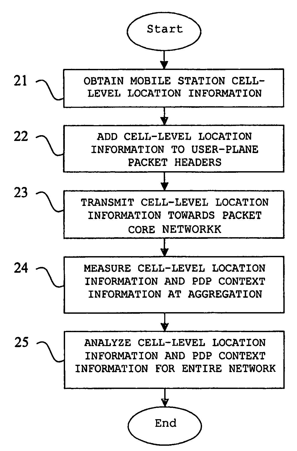
A method, network, and device for measuring and analyzing packet-switched traffic in a packet-switched radio telecommunication network. When cell-level location information for a mobile station (1) changes due to a handover, the location information is transmitted toward a packet core network (9) by adding the information to userplane packet headers such as a GPRS Tunneling Protocol (GTP) header (26). The measurement device measures the cell-level location information at a level (15b) in the network where the information from a plurality of mobile stations (1) is aggregated, together with PDP context information prior to analyzing information for the entire network.

Description

BACKGROUND OF THE INVENTION[0001]1. Technical Field of the Invention[0002]The present invention relates generally to mobile telecommunication networks. More particularly, and not by way of limitation, the invention is directed to a location-signaling system and method for large-scale end-to-end quality-of-service monitoring of packet-switched telecommunication networks.[0003]2. Description of Related Art[0004]The detailed analysis of live General Packet Radio System (GPRS) and UMTS networks is of increasing importance as traffic on these networks increases and traffic measurements become available. Traffic measurements from these networks are extremely useful when analyzing such areas as network utilization information, network performance information indicating whether the users are getting what they paid for or what they expect, bottleneck information identifying bottlenecks in the network, system enhancement information for enhancing the network so that identified problems are el...

Claims


Application Information

Patent Timeline
Patent Type & Authority Patents(United States)
IPC IPC(8): H04W4/00H04L12/28H04W24/00H04L12/56H04W60/04
CPCH04W60/04
Inventor MALOMSOKY, SZABOLCSSZABO, ISTVAN
Owner TELEFON AB LM ERICSSON (PUBL)
Learn More