Collecting trough construction easily accessible for cleaning

a technology of collecting troughs and cleaning troughs, which is applied in the field of material collection and conveying systems, can solve the problems of especially fortuitous removal, and achieve the effects of convenient access, quick and easy repositioning, and convenient cleaning

Inactive Publication Date: 2009-12-15
BLUE LEAF I P INC
View PDF26 Cites 9 Cited by
  • Summary
  • Abstract
  • Description
  • Claims
  • Application Information

AI Technical Summary

Benefits of technology

[0012]Preferably, the first and second ends of the auger trough base pan are configured to be complementarily engageable with the first and second cross-pieces to securably maintain such auger trough base pan in position therebetween during harvesting operations, with at least the second end being detachable or disengageable from the second cross-piece by the user at other times to permit the auger trough base pan to be generally accessibly tilted downwardly from the first end towards the second end thereof while the first end of the auger trough base pan remains at least loosely still engaged with the first cross-piece. Such configuration is preferably achieved such as by rotating the second end of the auger trough base pan downwardly about the at least still loosely engaged first end of the auger trough base pan, the effect of which is to incline the auger trough base pan downwardly from said first end towards its second end to permit cleaning of the auger trough base pan while the pan is in such an in-place position. Clean out of loose elements or particles remaining in the collecting auger troughs may often be able to be satisfactorily effected while the auger trough base pan is in such in-place clean-out position, and even some encrusted build-up may be able to be removed.
[0015]In the practice of the invention, at least one of the cross-pieces with which the auger trough base pan may be engaged may be the clean grain auger trough or the tailings auger trough of the collecting and conveying system of the combine. In such circumstance, the clean grain or tailings auger trough and the end of the auger trough base pan engaged therewith are preferably configured to be so matably engaged with one another that material in the collecting troughs may be easily conveyed from such collecting troughs into the clean grain or tailings auger trough, as may be appropriate, without introducing any obstructions to the passageways through the clean grain or tailings auger troughs that would hinder the conveyance of material therethrough. By way of example, the second end of the auger trough base pan and a side of the clean grain auger trough may employ interengageable lips thereon for mating the second end of the auger trough base pan to the clean grain auger trough, which second end connection pairing embodiment preserves and maintains a relatively smooth and uniform passageway through the clean grain auger trough when the second end of the auger trough base pan is mated to a side of the cross-wise extending clean grain auger trough.
[0018]For clean-out, the securing rod may be removed and the second end of the auger trough base pan may be disengaged from the second cross-piece, such as by the downward rotation of the second end of the auger trough base pan about the first end of the auger trough base pan. With the auger trough base pan in a tilted position, with the first end thereof remaining at least loosely engaged with the first cross-piece and the second end of the auger trough base pan resting upon or being in closer position to the ground, a user can relatively easily access the collecting troughs formed in the auger trough base pan for cleaning while the base pan remains in such in-place clean-out position. Especially if the remnants remaining in the collecting troughs are loose, as opposed to encrusted, remnants, the tilting of the base pan may be sufficient to effect the discharge of the loose remnants from the then-depending second end of the base pan, and little additional cleaning may be necessary prior to re-engagement of the second end of the base pan with the second cross-piece.
[0020]Once appropriate clean-out of the troughs of the auger trough base pan has been effected, either while the base pan is in its in-place clean-out position or after the totally removed base pan has been cleaned at some other desired location, the auger trough base pan can thereafter be quickly and easily re-positioned for re-installation and re-installed for further use.
[0021]With such a construction, the collecting troughs can be much more conveniently accessed than was previously the case, and clean out of the collecting troughs can be quickly and easily effected, without any extensive disassembly of the collecting and conveying systems or the need for any specialized tools, and without the accompanying time loss that resulted from such activities.

Problems solved by technology

Such removal is especially fortuitous when the remnant build-up in the collecting troughs is extensive or severe or when the cleaning activities would involve or require greater or more extended efforts by a user.

Method used


Image

  • Collecting trough construction easily accessible for cleaning
  • Collecting trough construction easily accessible for cleaning
  • Collecting trough construction easily accessible for cleaning

Examples


Embodiment Construction

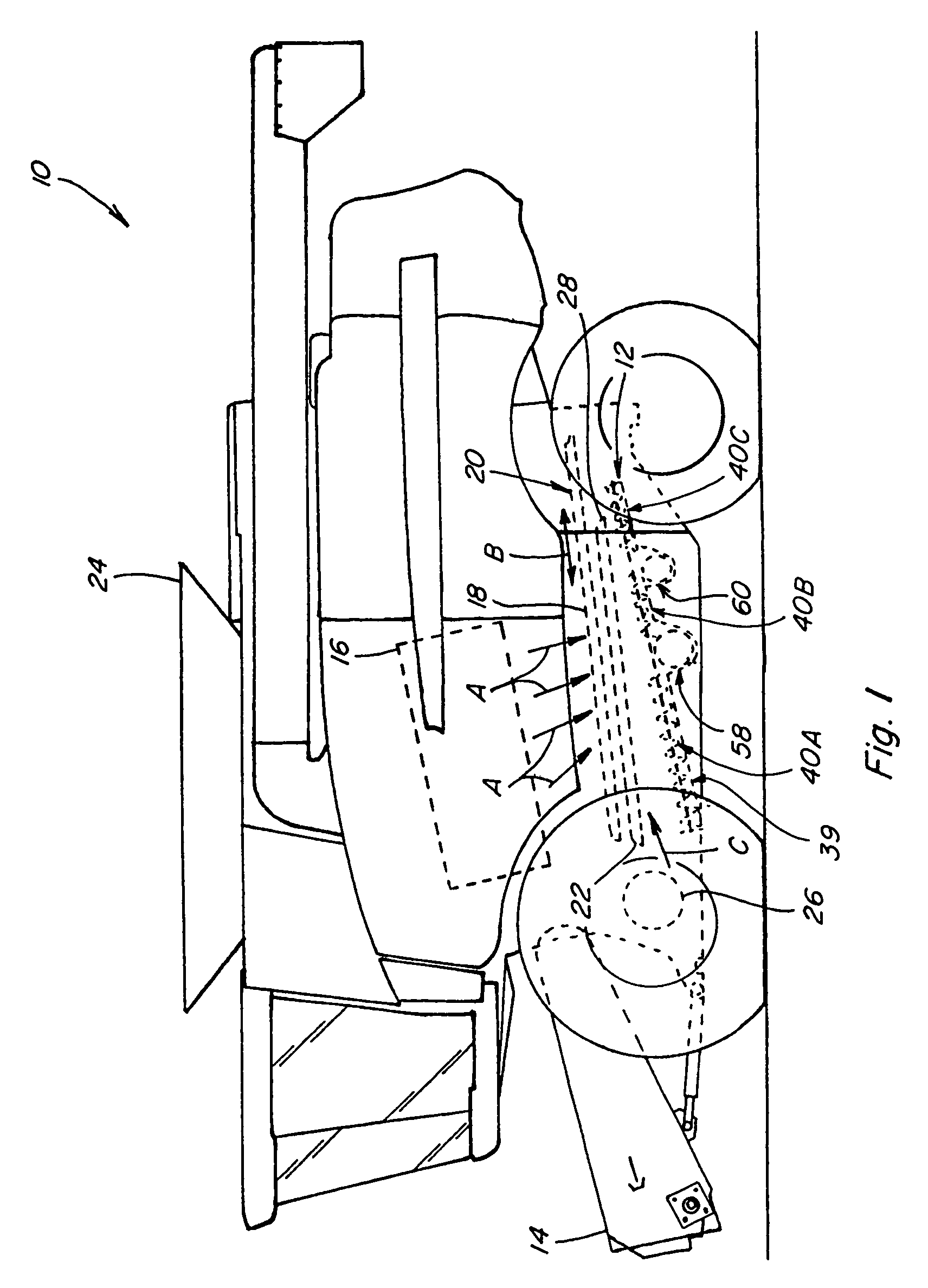
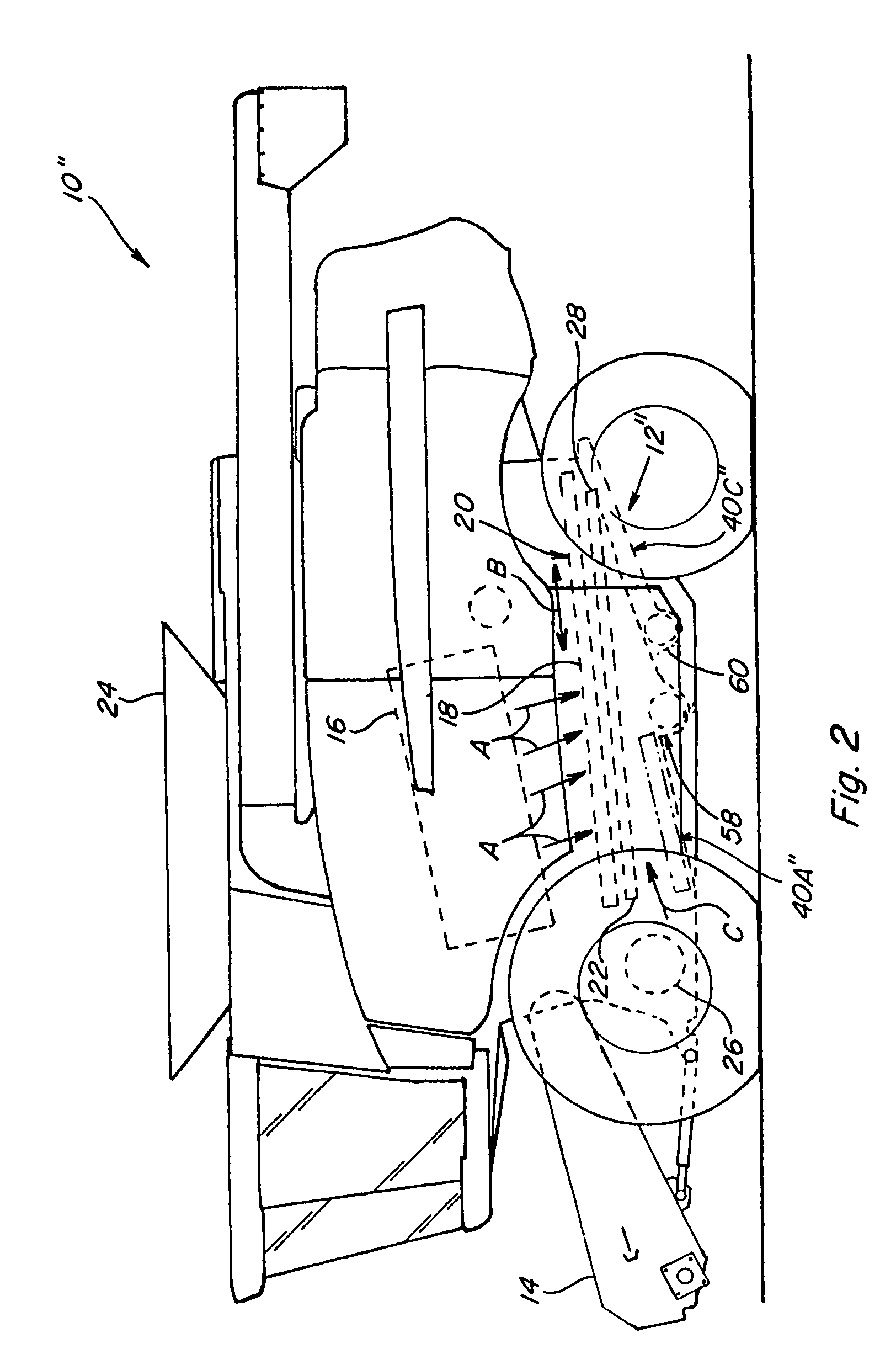
[0034]Referring now to the drawings, wherein like numbers refer to generally like items or features, FIGS. 1 and 2 depict generally similar agricultural combines 10 and 10″ that include similar, but somewhat different, respective clean grain and tailings collecting and conveying systems 12 and 12″, each of which systems 12 and 12″ include auger trough base pan constructions according to the present invention.

[0035]Combines 10 and 10″ are of conventional, well known construction, each including a feeder house 14 on a front end thereof, to which is connectable a header (not shown) operable to sever a swath of crops from a field as the combine is moved forwardly thereover and to convey the severed crops to feeder house 14. Feeder house 14 includes an internal conveying system (not shown) for conveying the crops upwardly and rearwardly into the bodies of the combines 10 and 10″, into an inlet of a separating or threshing system 16 of the combines. Threshing system 16 generally includes ...


PUM


Abstract

A collecting trough construction for facilitating the clean out of collecting troughs of clean grain and tailings collecting and conveying systems of agricultural combines, such collecting trough construction including a base pan sized and dimensioned to extend longitudinally between first and second cross-pieces of such a collecting and conveying system, one of which cross-pieces may be a clean grain auger trough or a tailings auger trough, and laterally generally between the sidesheets of a combine, with collecting troughs formed in the upper side thereof, which base pan has first and second ends and is positionable between the first and second cross-pieces with the first end of the auger trough base pan adjacent the first cross-piece and the second end of the auger trough base pan adjacent the second cross-piece to be readily complementarily engageable therewith and wholly or partially disengageable therefrom by a user to permit convenient access to the formed collecting troughs for cleaning thereof. Preferably, the base pan is, alternatively, partially detachable to permit access for cleaning by a user in an in-place clean-out position or wholly removable to permit the removal of such base pan to a remote location for cleaning by the user thereat.

Description

TECHNICAL FIELD[0001]This invention relates generally to material collecting and conveying systems of agricultural combines and to a construction for facilitating the clean out of the collecting troughs of such systems, and, more particularly, to a collecting trough base pan for such systems that has collecting troughs formed on the upper side thereof and which can be easily and quickly installed for use during harvesting operations and conveniently accessed or removed at different times for cleaning. Preferably, the base pan will be partially detachable or disengageable to permit the collecting troughs to be made accessible generally in-place for cleaning and also removable to permit remote cleaning of the collecting troughs of the base pan.BACKGROUND ART[0002]In the harvesting of crops it is desired that the grain be separated from other elements or portions of the crop, such as from pod or cob fragments, straw, stalks, and the like. Agricultural combines typically have employed a...

Claims


Application Information

Patent Timeline
Patent Type & Authority Patents(United States)
IPC IPC(8): A01B71/08
CPCA01F12/44
Inventor SCHMIDT, JAMES R.RICKETTS, JONATHAN E.MATOUSEK, ROBERT A.
Owner BLUE LEAF I P INC
Why Eureka
Try Eureka