Floating water turbine for a power plant

a technology of hydroelectric power generation and floating water turbine, which is applied in the direction of electric generator control, machines/engines, mechanical equipment, etc., can solve the problems of harris not teaching the concavity of the impeller blades or buoyancy, and the use of fossil fuels at an increasing ra

Inactive Publication Date: 2009-12-15
FEILER FRED JOHN
View PDF22 Cites 56 Cited by
  • Summary
  • Abstract
  • Description
  • Claims
  • Application Information

AI Technical Summary

Problems solved by technology

Not only are fossil fuels being consumed at an increasing rate, their use typically generates undesirable side effects: pollution.
Harris does not teach concavity of the impeller blades or buoyancy of the impellers themselves.

Method used


Image

  • Floating water turbine for a power plant
  • Floating water turbine for a power plant
  • Floating water turbine for a power plant

Examples


Embodiment Construction

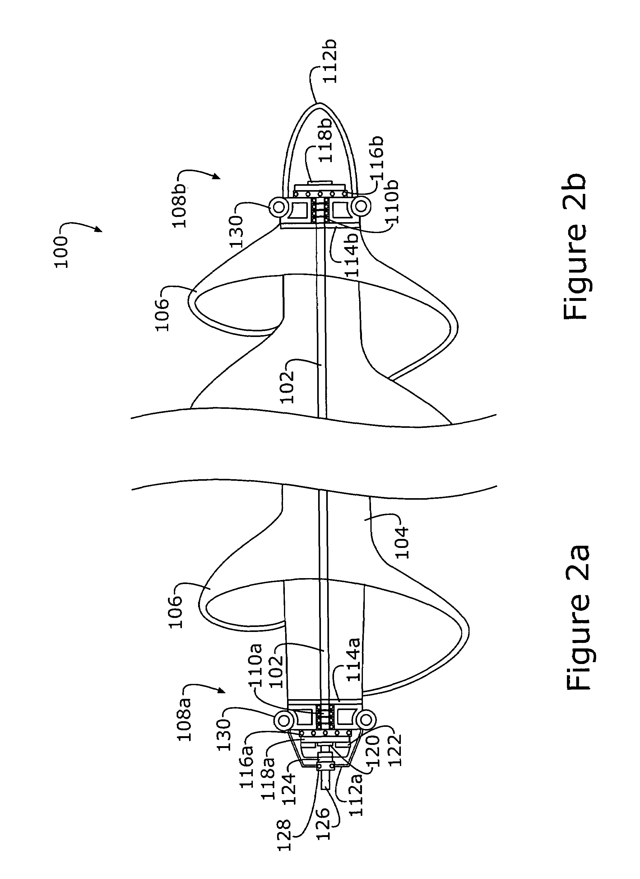
[0022]The rotating portion of the turbine is connected through a series of linkages to an electric generator that converts the mechanical energy into electric power. The force of flowing water causes the turbine to rotate, thus driving the linkages. Between the rotor and the linkages to the generator are disposed the necessary drive shaft mechanisms and a shielding device. The mechanisms connected to the rotor end may include a shaft outlet connector, a clutch, a brake, a thrust bearing, a turntable bearing, eyelets for hoist and pier connections.

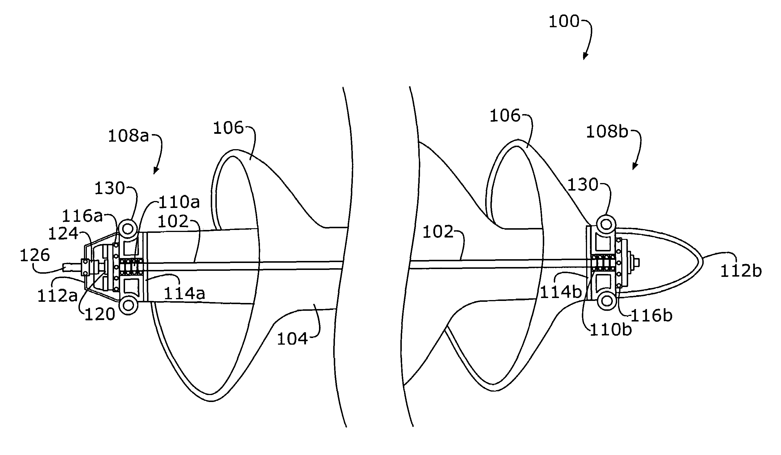
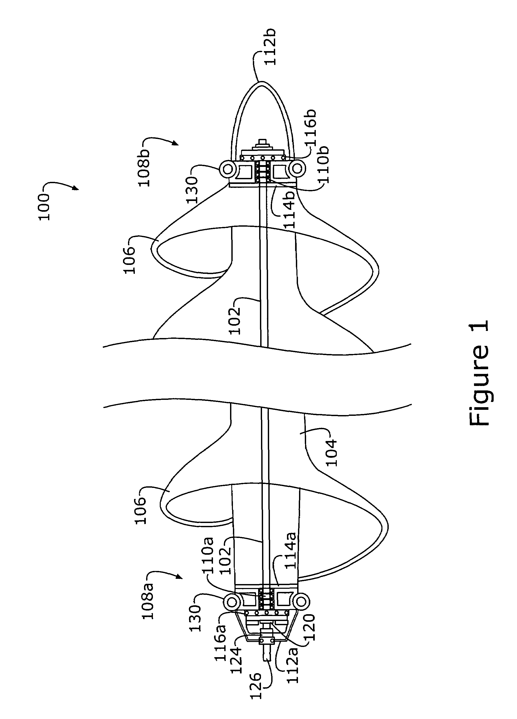
[0023]Referring first to FIG. 1, there is shown a quasi-perspective view of the turbine of the invention, including side elevational, cross-sectional views of the end regions thereof, generally at reference number 100.

[0024]Turbine 100 has a central shaft 102 disposed longitudinally in an elongated, buoyant housing 104 that is affixed thereto and rotative therewith. Elongated buoyant housing 104 and shaft 102 are designed to have a combined...


PUM


Abstract

An auger-type floating turbine having an elongated, buoyant rotating housing with one or more flights of blades, fins, or impellers supported on its outer surface is connected to an electrical generator to produce electrical power. The turbine may also be coupled to another machine such as a pump, compressor, etc. The turbine captures energy from a flowing stream of water. The rotor shaft is connected through a series of linkages to the electric generator that converts the mechanical energy into electric power. The force of water flowing causes the shaft to rotate, thus driving the linkages. Between the rotor shaft and the linkages to the generator are disposed drive shaft mechanisms and a shielding device. The mechanisms may include a shaft outlet connector, a shield connector, a thrust bearing and break, eyelets for hoist and pier connections, and a rear hoist eyelet.

Description

FIELD OF INVENTION[0001]This invention relates to electrical generation systems and, more particularly, to a floating hydroelectric power generation system for deployment in flowing water.BACKGROUND OF INVENTION[0002]With the increasing need for electrical power production and the decreasing availability of fossil fuels, alternative sources of energy must be developed. Fossil fuels currently make up over 65% of the fuels used to produce electricity in the United States. Not only are fossil fuels being consumed at an increasing rate, their use typically generates undesirable side effects: pollution. Due to this country's vast supply of flowing water, it is logical to develop systems that can harness the potential power “locked” within these flowing water resources. With the abundance of flowing water in many regions of the United States, power generated by harnessing the energy of flowing waterpower can help alleviate power distribution problems by bringing cogeneration closer to con...

Claims


Application Information

Patent Timeline
Patent Type & Authority Patents(United States)
IPC IPC(8): F03B13/12F03B13/10H02P9/04
CPCF03B17/061H02P9/04F05B2240/243H02P2101/10Y02E10/28Y02E10/30Y02E10/20
Inventor FEILER, FRED JOHN
Owner FEILER FRED JOHN
Why Eureka
Try Eureka