Driving device capable of transferring vibrations generated by an electro-mechanical transducer to a vibration friction portion with a high degree of efficiency

a technology of electro-mechanical transducers and driving devices, which is applied in piezoelectric/electrostrictive/magnetostrictive devices, piezoelectric/electrostriction/magnetostriction machines, electrical apparatus, etc., can solve the problems of not revealing nor teaching specific materials of driving members, and easily producing an unnecessary vibration mode, and achieves high efficiency.

a technology of electro-mechanical transducers and driving devices, which is applied in piezoelectric/electrostrictive/magnetostrictive devices, piezoelectric/electrostriction/magnetostriction machines, electrical apparatus, etc., can solve the problems of not revealing nor teaching specific materials of driving members, and easily producing an unnecessary vibration mode, and achieves high efficiency.

US7633208B2Inactive Publication Date: 2009-12-15MITSUMI ELECTRIC CO LTD

Image

  • Driving device capable of transferring vibrations generated by an electro-mechanical transducer to a vibration friction portion with a high degree of efficiency
  • Driving device capable of transferring vibrations generated by an electro-mechanical transducer to a vibration friction portion with a high degree of efficiency
  • Driving device capable of transferring vibrations generated by an electro-mechanical transducer to a vibration friction portion with a high degree of efficiency

Examples


Embodiment Construction

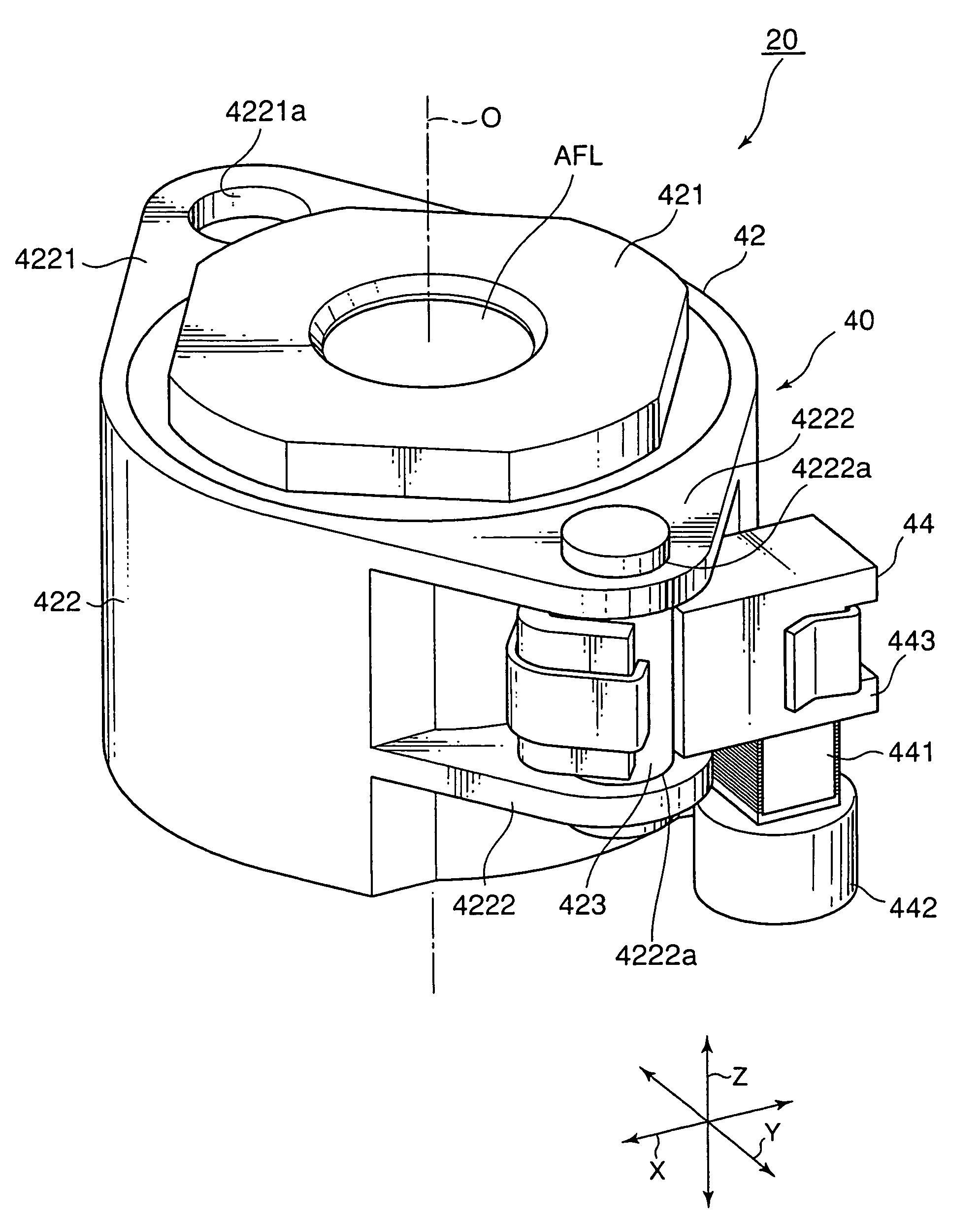
[0035]FIG. 1 is an external perspective view of a driving device 20 according to an exemplary embodiment of this invention. Herein, in the manner shown in FIG. 1, an orthogonal coordinate system (X, Y, Z) is used. In a state illustrated in FIG. 1, in the orthogonal coordinate system (X, Y, X), an X-axis direction is a fore-and-aft direction (a depth direction), a Y-axis direction is a left-and-right direction (a width direction), and a Z-axis direction is an up-and-down direction (a height direction). In addition, in the example being illustrated in FIG. 1, the up-and-down direction Z is a direction of an optical axis O of a lens.

[0036]The driving device 20 is covered with a cabinet (not shown). The cabinet includes a cap-shaped upper cover (not shown) and a lower base (not shown). On the lower base of the cabinet, a stationary member (a weight) 442 which will later be described is mounted. The upper cover has an upper surface comprising a cylinder portion (not shown) having a cente...


PUM


Abstract

A driving device includes an electro-mechanical transducer having first and second end portions opposite to each other in an expansion / contraction direction, a stationary member coupled to the first end portion of the electro-mechanical transducer, a vibration friction portion coupled to the second end portion of the electro-mechanical transducer, and a rod-shaped moving portion frictionally coupled to the vibration friction portion, whereby moving the moving portion in the expansion / contraction direction of the electro-mechanical transducer. The vibration friction portion is made of a material having a vibration transfer rate of 4900 meters / second or more. The moving portion is made of a material which has a vibration transfer rate of 4900 meters / second or more and which is different from that of the vibration friction portion.

Description

[0001]This application is based upon and claims the benefit of priority from Japanese Patent Application JP 2007-107785, filed on Apr. 17, 2007, the disclosure of which is incorporated herein in its entirety by reference.BACKGROUND OF THE INVENTION[0002]This invention relates to a driving device (a linear actuator) and, in; particular, to a driving device where an electro-mechanical transducer such a piezoelectric element is used as a driving source of the driving device (the linear actuator).[0003]Previously, linear actuators (driving devices) using electro-mechanical transducers such as piezoelectric elements, electrostrictive elements, magnetostrictive elements, or the like are used as auto-focus actuators or zoom actuators for use in cameras.[0004]By way of illustration, Japanese Patent No. 2633066 (JP-B 2633066) (which will be also called a first patent document), which corresponds to U.S. Pat. No. 5,225,941, discloses a driving device comprising a driving rod frictionally enga...

Claims


Application Information

Patent Timeline
15 Dec 2009
Publication
US7633208B2
IPC
H01L41/08; H02N2/00
CPC
H02N2/025; H02N2/007
Inventors
YAMADA, TSUKASA; NISHIYAMA, TAKAHIKO