Wire-wound coil

a wire-wound coil and coil technology, applied in the direction of transformer/inductance details, fixed inductances, inductances, etc., can solve the problems of reducing reliability, magnetic flux leakage, and reducing so as to improve the efficiency of obtaining inductance, reduce magnetic flux leakage, and increase effective magnetic permeability

Active Publication Date: 2009-12-15
MURATA MFG CO LTD
View PDF22 Cites 6 Cited by
  • Summary
  • Abstract
  • Description
  • Claims
  • Application Information

AI Technical Summary

Benefits of technology

[0009]To overcome the problems described above, preferred embodiments of the present invention provide a wire-wound coil capable of reducing magnetic flux leakage from a joint portion between a flange portion of a core and a ferrite plate to increase effective magnetic permeability, and therefore, to improve the efficiency of obtaining inductance.
[0015]According to preferred embodiments of the present invention, a wire-wound coil capable of reducing magnetic flux leakage from a joint portion between a flange portion of a core and a ferrite plate to increase effective magnetic permeability, and therefore, capable of improving the efficiency of obtaining inductance is obtained.

Problems solved by technology

However, this common-mode filter is different from the high-frequency common-mode choke coil of Japanese Unexamined Patent Application Publication No. 2003-168611 in that flange portions of a core and a ferrite plate are joined to each other by an adhesive through recessed and projecting portions.
Magnetic flux leaks from this space, and the efficiency of obtaining inductance is reduced.
For a similar reason, the common-mode filter of Japanese Unexamined Patent Application Publication No. 2005-056934 also causes magnetic flux leakage.
If the gaps are minimized, however, the joining strength between the drum core 6 and the return magnetic path member 8 is reduced, resulting in reduced reliability.
It is therefore difficult to use a thick wire and a desired number of winding turns may not be obtained.

Method used


Image

  • Wire-wound coil
  • Wire-wound coil
  • Wire-wound coil

Examples


first preferred embodiment

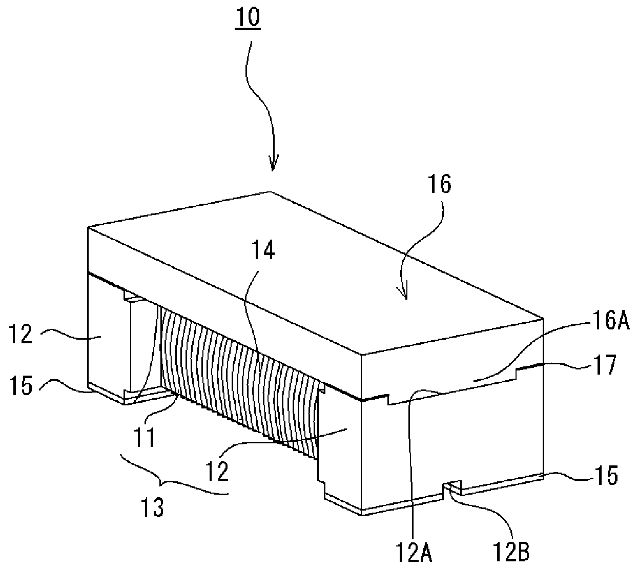
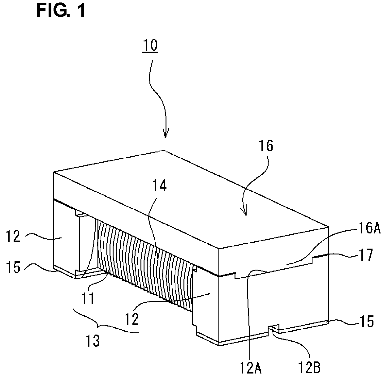
[0028]As shown in FIGS. 1 and 2A to 2C, a wire-wound coil 10 of this preferred embodiment includes, for example, a ferrite core 13 having a winding core portion 11 and flange portions 12 provided at both ends thereof, an insulation-coated winding (hereinafter referred to as a “wire”) 14 wound around the winding core portion 11 of the ferrite core 13, electrodes 15 provided on lower surfaces of the flange portions 12 and connected to the ends of the wire 14, and a ferrite plate 16 that extends over the winding core portion 11 in a longitudinal direction and is joined to upper surfaces of the flange portions 11B defined at the ends thereof.

[0029]As shown in FIGS. 1 and 2A, a recessed portion 12A is provided at a center portion of the upper surface of each of the flange portions 12, and a recessed portion 12B, which is narrower than the recessed portions 12A, is provided at a center portion of the lower surface of each of the flange portions 12. As shown in FIGS. 2A and 2B, the recesse...

second preferred embodiment

[0034]It was discovered that the wire-wound coil 10 of the first preferred embodiment might cause a reduction of inductance because the pressure applied when the ferrite core 13 and the ferrite plate 16 are combined might cause the adhesive 17 to flow into the joining surfaces of the winding portion and the recessed and projecting portions 12A and 16A due to capillary effect. A wire-wound coil of this preferred embodiment is configured such that sections at which a ferrite core and a ferrite plate are adhered are specifically designed to overcome such a problem. In describing the wire-wound coil of this preferred embodiment, portions of the wire-wound coil corresponding to those of the first preferred embodiment are denoted by the same numerals, and the characteristic features of the wire-wound coil of this preferred embodiment will primarily be described.

[0035]As shown in FIG. 3A, a wire-wound coil 10A of this preferred embodiment includes improved adhesion portions 12C of the flan...

example 1

[0042]In this example, the configuration of the ferrite core 13 was changed so as to change the ratio (B / A) of the size B of each of the flange portions on the upper surface of the ferrite core 13 to the size A of each of the flange portions on the lower surface thereof in the manner shown in FIG. 6, and the inductance of the wire-wound coil with respect to each of the ratios (B / A) was measured. As a result of the measurement, the results shown in FIG. 6 were obtained. According to the results shown in FIG. 6, the inductance value significantly changes when the configuration ratio (B / A) of the ferrite core 13 ranges from about 0.5 to about 1, and the inductance value changes by only a small amount, with a tendency to gradually reach a saturation region, when the configuration ratio (B / A) exceeds about 1. Therefore, it was found that a desired inductance value could be efficiently obtained by setting the configuration ratio (B / A) of the ferrite core 13 to about 1 or less.


PUM

PropertyMeasurementUnit
heightaaaaaaaaaa
widthaaaaaaaaaa
widthaaaaaaaaaa

Abstract

A wire-wound coil includes a ferrite core having a winding core portion and flange portions, a wire wound around the winding core portion, electrodes connected to the wire on lower surfaces of the flange portions, and a ferrite plate attached to upper surfaces of both of the end flange portions so as to extend over the winding core portion. The flange portions and the ferrite plate are provided with corresponding recessed and projecting portions and, and the flange portions and the ferrite plate are integrated through the recessed and projecting portions. Joint sections between the flange portions and the ferrite plate include contact sections that are in direct contact with each other, and adhesion sections arranged to receive an adhesive.

Description

BACKGROUND OF THE INVENTION[0001]1. Field of the Invention[0002]The present invention relates to wire-wound coils, and more specifically, to a wire-wound coil capable of reducing magnetic flux leakage to improve the efficiency of obtaining inductance.[0003]2. Description of the Related Art[0004]Known wire-wound coils of this type include common-mode choke coils described in, for example, Japanese Unexamined Patent Application Publication No. 2003-168611, Japanese Unexamined Patent Application Publication No. 10-163029, and Japanese Unexamined Patent Application Publication No. 2005-056934. As shown in, for example, FIG. 10A, a high-frequency common-mode choke coil described in Japanese Unexamined Patent Application Publication No. 2003-168611 includes a core 1 having a winding core portion 1A and flange portions 1B, a wire 2 wound around the winding core portion 1A of the core 1, electrodes 3 provided on lower surfaces of the flange portions 1B of the core 1, and a ferrite plate 5 a...

Claims


Application Information

Patent Timeline
Patent Type & Authority Patents(United States)
IPC IPC(8): H01F27/02
CPCH01F17/045H01F3/12H01F27/263
Inventor HIRAI, SHINYATOI, TAKAOMI
Owner MURATA MFG CO LTD
Why Eureka
Try Eureka