Multilayer interference filter for photochromic lenses

a multi-layer interference and filter technology, applied in the field of optical quality, can solve the problems of significantly unable to meet the requirements of these treatments, and unable to achieve the effect of affecting the original photochromic activity of the lens

Active Publication Date: 2009-12-15
INERCAST USA INC
View PDF7 Cites 10 Cited by
  • Summary
  • Abstract
  • Description
  • Claims
  • Application Information

AI Technical Summary

Benefits of technology

[0011]The present invention relates to new optical-quality multi-layer interference films, and, in particular, to new optical-quality multi-layer interference films for use with photochromic sunglass and ophthalmic lenses, visors, masks, screens and the like. In particular, the present invention relates to new optical quality multi-layer interference films that are selected and deposited in such a way so as to not adversely affect the original photochromic activity of the lens. To obtain this objective, a preferred embodiment of the present invention is directed to a thin film having a plurality of layers of dielectrics which can maintain or enhance the penetration of UVA radiation preferably within a range from 315 to 400 nm, more preferably within a range from 350 to 380 nm, i.e., the interval of wavelengths responsible for the activation of the photochromic molecules.

Problems solved by technology

Photochromic lenses, however, are not as compatible with these treatments.
The treatment on the outer surface of photochromic lenses can significantly impede photochromic activity and inhibit darkening of the lenses when the lenses are exposed to sunlight.

Method used


Image

  • Multilayer interference filter for photochromic lenses
  • Multilayer interference filter for photochromic lenses
  • Multilayer interference filter for photochromic lenses

Examples


example 1

The Silver Mirror effect is obtained by depositing the following 12 layers of SiO2 and TiO2 on an ADC lens:

[0033]

LayerMaterialThickness (nm)1TiO23.242SiO222.413TiO26.124SiO221.215TiO233.86SiO214.947TiO229.858SiO2102.429TiO224.6110SiO27.5311TiO29.1312SiO229.38Medium: Air

[0034]Table 2 below shows the activation % of Example 1 compared to the Activation of the same lens uncoated.

[0035]

TABLE 2PhotochromicUncoated lensExample 1lens typeActivation (%)Activation (%)ADC52%53%

[0036]FIG. 5 shows the reflectance curve of example 2, which is an ADC lens coated with a film having a UVA reflectance of less than 6% in the range from about 315 to 400 nm, in accordance with an embodiment of the present invention. The film provides the lens with the appearance substantially resembling the prior art “White Silver” decorative coating of FIG. 3.

example 2

[0037]The film, in accordance with an embodiment of the present invention, comprises the following 12 layers of TiO2, ZrO2 and SiO2 dielectrics deposited on an ADC lens:

[0038]

LayerMaterialThickness (nm)1TiO24.352SiO217.93TiO29.594SiO231.35ZrO222.66SiO229.77TiO233.058SiO2106.669TiO225.1510SiO222.9511ZrO210.2312SiO23.33Medium: Air

[0039]Table 3 below shows the activation % of Example 2 compared to the activation % of the same lens uncoated and the same lens coated with the prior art “White Silver” coating.

[0040]

TABLE 3LensLens coated withcoated withprior artPhotochromicUncoated lensExample 2“White Silver” coatinglens typeActivation (%)Activation (%)Activation (%)ADC52%52%7%

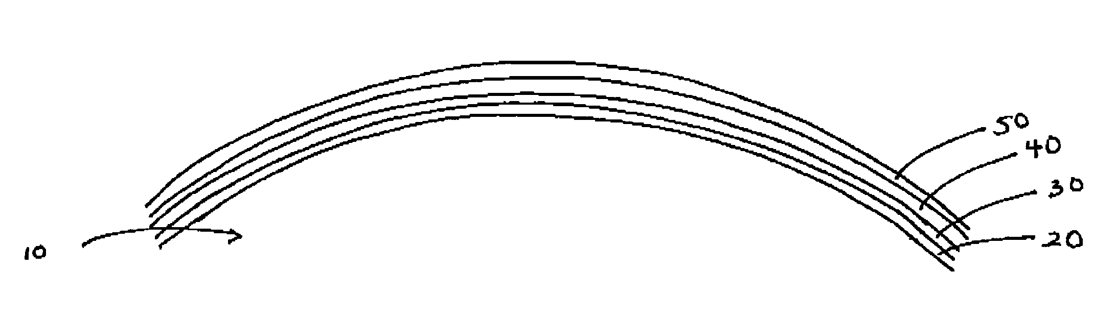
[0041]FIG. 6 shows the reflectnce curve of Example 3, which is an ADC lens coated With an antireflective coating with a reflectance less than 15% in the range of about 350 to 400 nm, in accordance with an embodiment of the present invention. Referring to FIG. 7, dielectric layers 20, 30, 40, 50 are deposited on a len...

example 3

[0042]The antireflective coating is obtained depositing four alternating layers of TiO2 and SiO2 dielectrics on an ADC lens in the following order:

[0043]

LayerMaterialThickness1TiO212.262SiO229.593TiO290.694SiO278.90Medium: Air

[0044]Table 4 below shows the Activation of Example 3 compared to the same lens uncoated. The results of Table 4 illustrate that Example 3 permits the lens to be coated with an antireflective coating without losing any photochromic activation.

[0045]

TABLE 4PhotochromicUncoated lensExample 3lensActivation (%)Activation (%)ADC52%52%

[0046]The previous examples disclose three different multilayer coatings, in accordance with the invention, for use with photochromic lenses which do not adversely affect their photochromatic activity. This result is obtainable by selecting and arranging each layer in order to maintain the Reflectance preferably under 15% and more preferably under 6% preferably in the range from about 315 to 400 nm and more preferably in the range from ...


PUM

PropertyMeasurementUnit
specific wavelengthsaaaaaaaaaa
wavelengthsaaaaaaaaaa

Abstract

A multi-layer thin film is provided preferably for use with photochromic lenses, wherein the thin film comprises a plurality of layers, preferably including dielectric layers, selected and arranged so as to reflect less than about 6 percent of the UVA rays in a range of about 315 to 400 nm, more preferably about 350 to 380 nm. The thin film preferably has an activation value greater than 25%.

Description

CROSS-REFERENCE TO RELATED APPLICATION[0001]This application claims the benefit of U.S. Provisional Application Ser. Nos. 60 / 457,882, filed Mar. 26, 2003 and 60 / 458,125, filed Mar. 27, 2003, both of which are entitled MULTILAYER INTERFERENCE FILTER FOR PHOTOCHROMIC LENSES, which are incorporated herein by reference.FIELD OF THE INVENTION[0002]The present invention relates to optical-quality, multi-layer interference films, and, in particular, to optical quality multi-layer interference films for use with photochromic sunglass lenses, ophthalmic lenses, visors, masks, screens and the like.BACKGROUND OF THE INVENTION[0003]High vacuum vapor deposition is used for the production of thin film layers for many industrial applications. In the optics field, sophisticated coating designs consisting of up to 100 single layers are employed in the production of multi-layer interference filters and antireflection coatings for use with prescription and sunglass lenses.[0004]Evaporants are metals, ...

Claims


Application Information

Patent Timeline
Patent Type & Authority Patents(United States)
IPC IPC(8): G02B1/10F21V9/04G02B5/28
CPCG02B5/283G02B5/0833
Inventor MARUSI, GRAZIANOMENTA, FEDERICOBAIOCCHI, PAOLO
Owner INERCAST USA INC
Why Eureka
Try Eureka