
Optimization-based modular control system

a modular control system and optimization-based technology, applied in the direction of adaptive control, electric controllers, instruments, etc., can solve the problems of lack of design and/or strategy that optimizes the overall force, moment or generalized effect of the system using the actuators, and is not cost-effective and practical control system

Inactive Publication Date: 2009-12-15
RGT UNIV OF MICHIGAN +1
View PDF10 Cites 29 Cited by
  • Summary
  • Abstract
  • Description
  • Claims
  • Application Information

AI Technical Summary

Benefits of technology

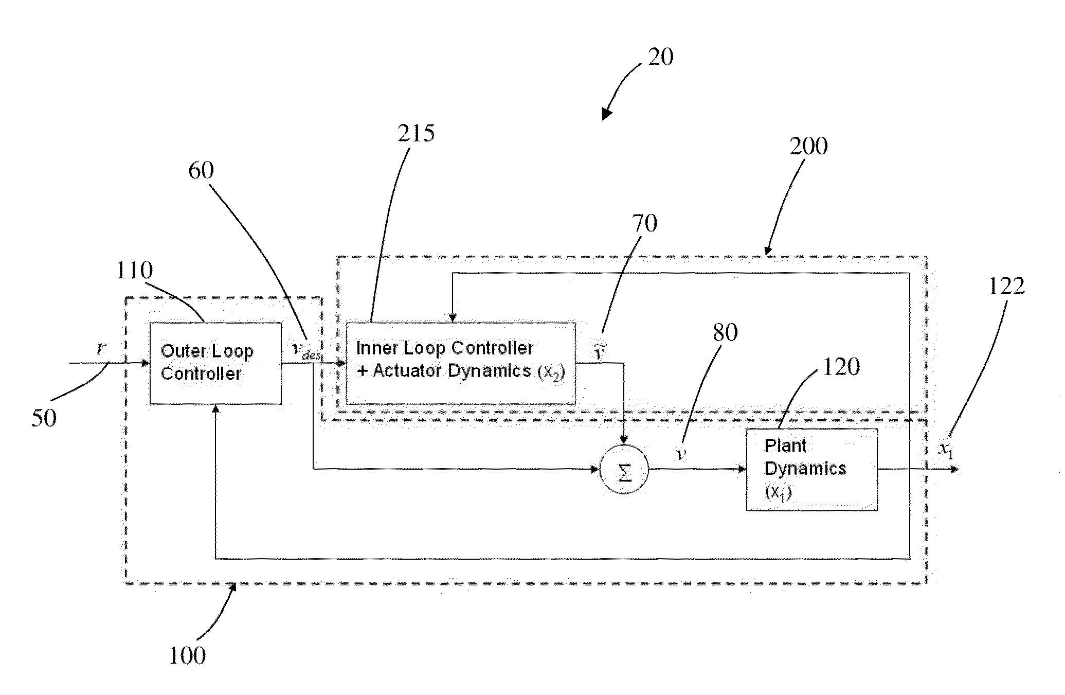
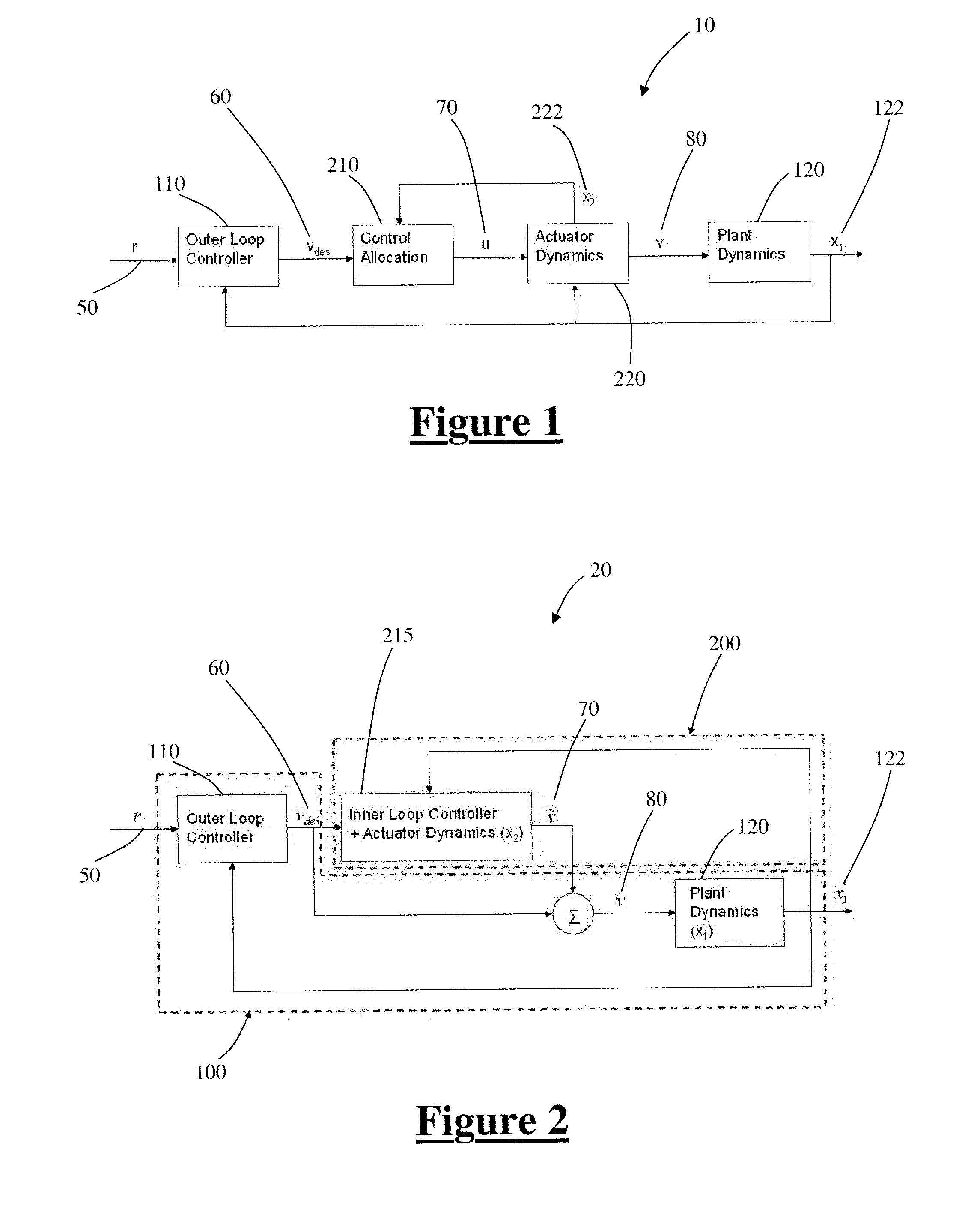
The patent describes a system for controlling a plant process using multiple actuators. The system includes an outer-loop controller that compares the plant's performance with a reference set point and provides a virtual control input to an inner-loop controller. The inner-loop controller then sends real control inputs to the N+1 actuators, which in turn provide an actual virtual control input to the plant. This results in the plant producing updated values of the N performance variables in an optimized manner. The technical effect of this system is improved control over the plant process using multiple actuators.

Problems solved by technology

However, a cost effective and practical control system, method of design and / or strategy that optimizes an overall force, moment or generalized effect using actuators of the system is lacking.

Method used


Image

  • Optimization-based modular control system
  • Optimization-based modular control system
  • Optimization-based modular control system

Examples


example

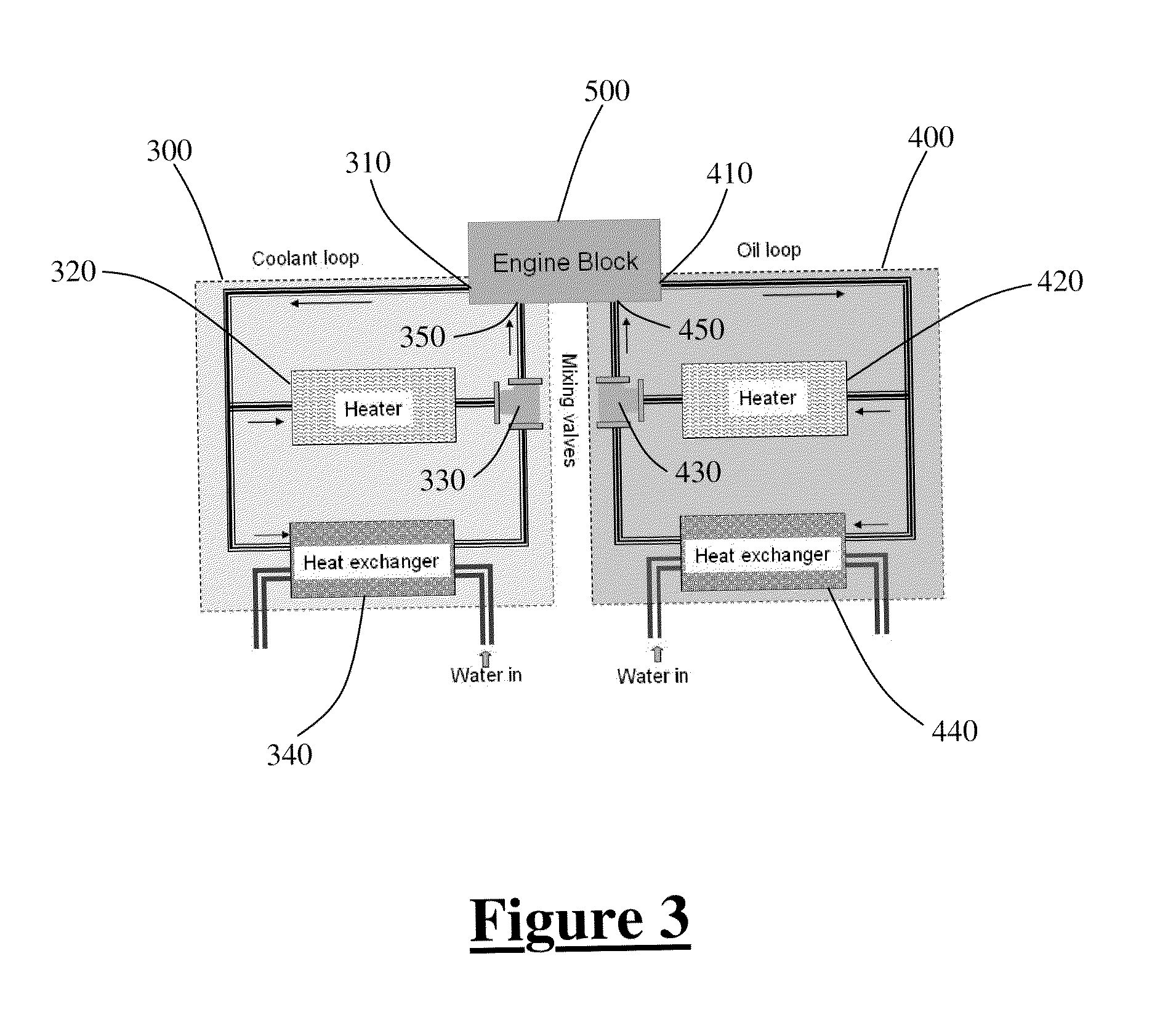
[0027]FIG. 3 illustrates an over-actuated plant in the form of a thermal system. The thermal system shown generally at 20 includes a coolant loop 300 and an oil loop 400. Both the coolant loop 300 and oil loop 400 include an engine outlet, 310 and 410 respectively. The coolant loop 300 also includes a heater 320, a mixing valve 330 and a heat exchanger 340. The oil loop 400 includes a heater 420, a mixing valve 430 and a heat exchanger 440. Upon operation of the engine block 500, coolant and oil pass through said block 500 and the various components of the respective loop.

[0028]Although different constraints may be placed on the coolant loop 300 and oil loop 400, the engine block 500 will have one engine outlet temperature at engine outlet 310 and engine outlet 410. In addition, the heater 320 and mixing valve 330 serve as actuators to the engine block 500 wherein said components can be used to vary the engine inlet temperature at 350. Likewise, the heater 420 and mixing valve 430 c...


PUM


Abstract

A system for controlling a plant process wherein the plant is over-actuated with N+1 actuators and provides N performance variables is disclosed. The system includes an outer-loop controller operable to compare N performance variable values from the plant with a reference set point and provide a desired virtual control input to an inner-loop controller. The inner-loop controller receives the desired virtual control input from the outer-loop controller and provides real control inputs to the at least N+1 actuators. The N+1 actuators receive the real control inputs and subsequently provide an actual virtual control input to the plant. Upon receiving the actual virtual control input from the N+1 actuators the plant is operable to produce N updated performance variable values in an optimized manner.

Description

FIELD OF THE INVENTION[0001]This invention relates generally to a control system for an automotive plant. More specifically, the invention relates to an inner-loop / outer-loop control system for an automotive plant process.BACKGROUND OF THE INVENTION[0002]In order to meet performance, efficiency, emission and other possible requirements over a wide range of operating conditions and environments, an automotive system may have more input variables than output variables. The input variables to a plant, controlled using actuators, are used to control the output variables of the plant process. For example, a conventional gasoline engine will have at a minimum, throttle, spark advance and fuel inputs in order to control the speed and / or the air / fuel ratio of the engine. In more advanced engines, variable valve timing (VVT) and continuously variable transmissions (CVTs) represent additional control inputs that may be applied to a plant.[0003]The excess of inputs, and thus excess of actuator...

Claims


Application Information

Patent Timeline
Patent Type & Authority Patents(United States)
IPC IPC(8): G05B13/02
CPCG05B11/32
Inventor VERMILLION, CHRISTOPHER R.SUN, JINGBUTTS, KEN R.
Owner RGT UNIV OF MICHIGAN
Learn More