AI technical title is built by Patsnap AI team. It summarizes the technical point description of the patent document.
a technology of viscometer and line material, applied in the field of viscometer, can solve the problem of considerable expense incurred in the use of additional line material
Active Publication Date: 2009-12-22
ENDRESS HAUSER FLOWTEC AG
View PDF17 Cites 16 Cited by
Summary
Abstract
Description
Claims
Application Information
AI Technical Summary
This helps you quickly interpret patents by identifying the three key elements:
Problems solved by technology
Method used
Benefits of technology
Benefits of technology
[0022]Through the invention, a marketable two-wire viscometer is provided for the first time; this is a basic advantage of the invention. The two wires serve both to supply the required power, for which purpose an external power source, generally a DC source, has to be connected to the two wires, and to transmit the output current, i.e., the viscosity signal in this invention.
[0023]Preferably, the two-wire viscometer is so designed that the output current flowing in the two wires represents, and particularly is proportional to, a signal generated by means of a physical-to-electrical transducer. In the case of this invention, the physical-to-electrical transducer is the at least one flow tube, and the output current is the viscosity signal. In the case of two-wire meters according to the above-mentioned 4- to 20-mA current standard, a given current value within this current range corresponds to exactly one output signal value, i.e., to exactly one value of the viscosity signal in this invention. Only the current range below 4 mA is usable for the supply of power to the electronics of the two-wire viscometer. As a result, the power supply only makes available power on the order of 50 mW, which will hereinafter be referred to as “low power”. In view of these facts, a two-wire viscometer with the aforementioned 4- to 20-mA current standard is particularly suited for use in potentially explosive atmospheres, so that such a two-wire viscometer can meet the requirements of the various classes of explosion protection.
[0024]Furthermore, the two-wire viscometer can be designed in a simple manner to be capable of cooperating with one of the conventional field buses. This can be accomplished by connecting the meter to the field bus directly, e.g., according to the Fieldbus protocol (Fieldbus is a registered trademark of Fieldbus Foundation), or indirectly via a bus coupler. e.g., according to the so-called HART protocol (HART is a registered trademark of the HART User Group).
Problems solved by technology
Particularly if several such viscometers are used in a plant and / or if viscometers are installed at a location remote from the external power supply, the use of additional line material will entail considerable expense.
Method used
Image
Click on the blue label to locate the original text in one second.
Reading with bidirectional positioning of images and text.
Examples
Embodiment Construction
[0037]While the invention is susceptible to various modifications and alternative forms, exemplary embodiments thereof have been shown by way of example in the drawings and will herein be described in detail. It should be understood, however, that there is no intent to limit the invention to the particular forms disclosed, but on the contrary, the intention is to cover all modifications, equivalents, and alternatives falling within the spirit and scope of the invention as defined by the intended claims.
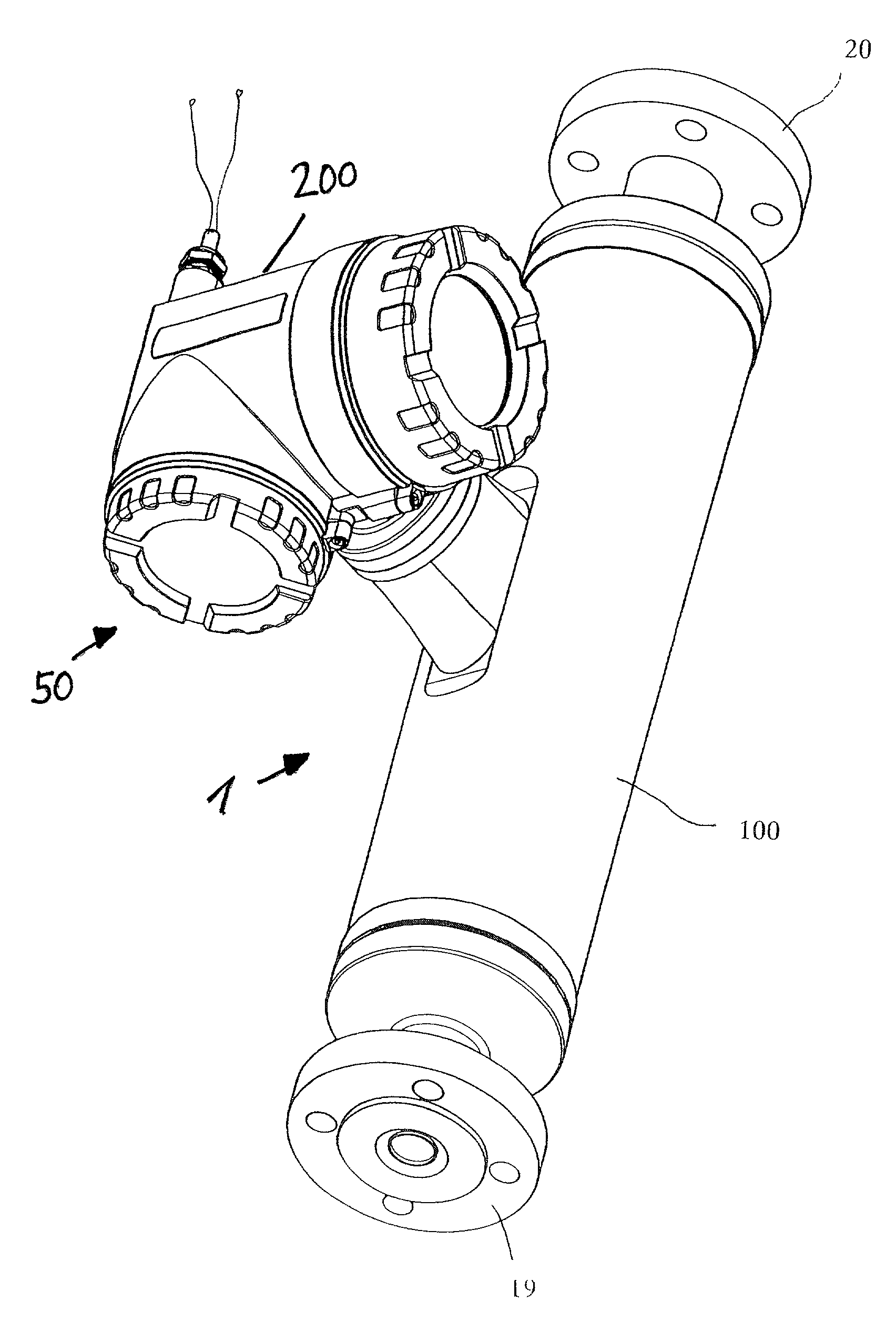
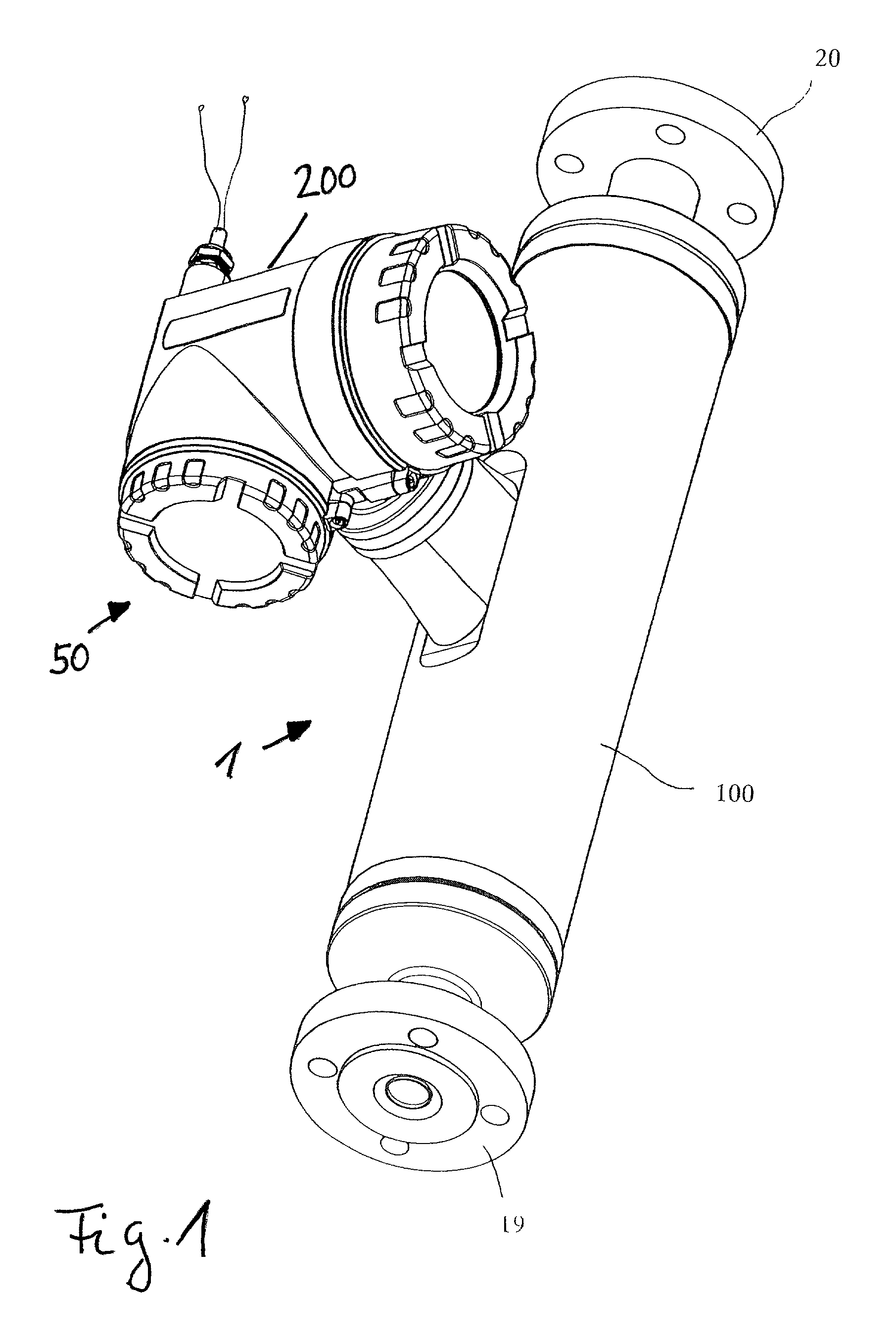
[0038]FIG. 1 shows a viscometer 1 with a vibratory transducer, preferably housed in a transducer case 100, and with meter electronics 50, housed in an electronics case 200 and electrically connected to transducer; meter electronics 50 are described in detail below.
[0039]Viscometer 1 serves to sense a viscosity of a fluid flowing in a pipe and to convert this viscosity into a viscosity value X; the pipe is not shown for the sake of clarity. By means of the transducer, which is excited ...
PUM
Property
Measurement
Unit
current
aaaaa
aaaaa
resonance frequency
aaaaa
aaaaa
current
aaaaa
aaaaa
Abstract
The viscometer comprises a vibratory transducer with at least one flow tube for conducting a fluid to be measured and for producing friction forces acting in the fluid. To vibrate the at least one flow tube, an excitation assembly is provided, which in operation is traversed by an excitation current. To generate the excitation current and a viscosity value representing the viscosity of the fluid, the viscometer includes meter electronics which are connected to, and supplied with electric power from, a two-wire process control loop. The meter electronics feed a viscosity signal corresponding to the measured viscosity value into the two-wire process control loop. The viscometer is suitable for measuring a fluid flowing in a pipe, particularly in potentially explosive atmospheres.
Description
[0001]This application is a non-provisional application of provisional application Ser. No. 60 / 301,013, filed Jun. 26, 2001 and provisional application Ser. No. 60 / 330,657, filed Oct. 26, 2001.FIELD OF THE INVENTION[0002]This invention relates to a viscometer for a fluid flowing in a pipe.BACKGROUND OF THE INVENTION[0003]In measurement and automation technology, the viscosity of a fluid flowing in a pipe, particularly of a liquid, is frequently determined by means of meters which, using a rotary transducer or a vibratory transducer and meter electronics connected thereto, induce internal friction forces in the fluid and derive therefrom a viscosity signal corresponding to the respective viscosity.[0004]Such viscometers and methods of measuring viscosity by means of such meters are described, for example, in U.S. Pat. Nos. 4,524,610, 4,704,898, 4,754,640, 4,920,787, 4,922,745, 5,157,962, 5,228,331, 5,448,921, in WO-A 95 / 16897, EP-A 527 176 or in EP-A 1 158 289 as well as in European ...
Claims
Application Information
Patent Timeline
Application Date:The date an application was filed.
Publication Date:The date a patent or application was officially published.
First Publication Date:The earliest publication date of a patent with the same application number.
Issue Date:Publication date of the patent grant document.
PCT Entry Date:The Entry date of PCT National Phase.
Estimated Expiry Date:The statutory expiry date of a patent right according to the Patent Law, and it is the longest term of protection that the patent right can achieve without the termination of the patent right due to other reasons(Term extension factor has been taken into account ).
Invalid Date:Actual expiry date is based on effective date or publication date of legal transaction data of invalid patent.

