Syringe pumps

a technology of syringe and pump, which is applied in the direction of flow monitors, medical devices, flow control, etc., can solve the problems of presenting a patient's hazard and the medication fluid upstream of the occlusion is subject to compressive forces, and achieve the effect of reducing the excess pressure of the medication

Inactive Publication Date: 2009-12-22
SMITHS MEDICAL INT
View PDF21 Cites 30 Cited by
  • Summary
  • Abstract
  • Description
  • Claims
  • Application Information

AI Technical Summary

Benefits of technology

[0007]According to a second aspect of the present invention there is provided a method of controlling a syringe pump including the steps of applying a force to drive a plunger along a barrel of a syringe to dispens

Problems solved by technology

When the pump is stopped, therefore, the medication fluid upstream of the occlusion is su

Method used


Image

  • Syringe pumps
  • Syringe pumps

Examples


Embodiment Construction

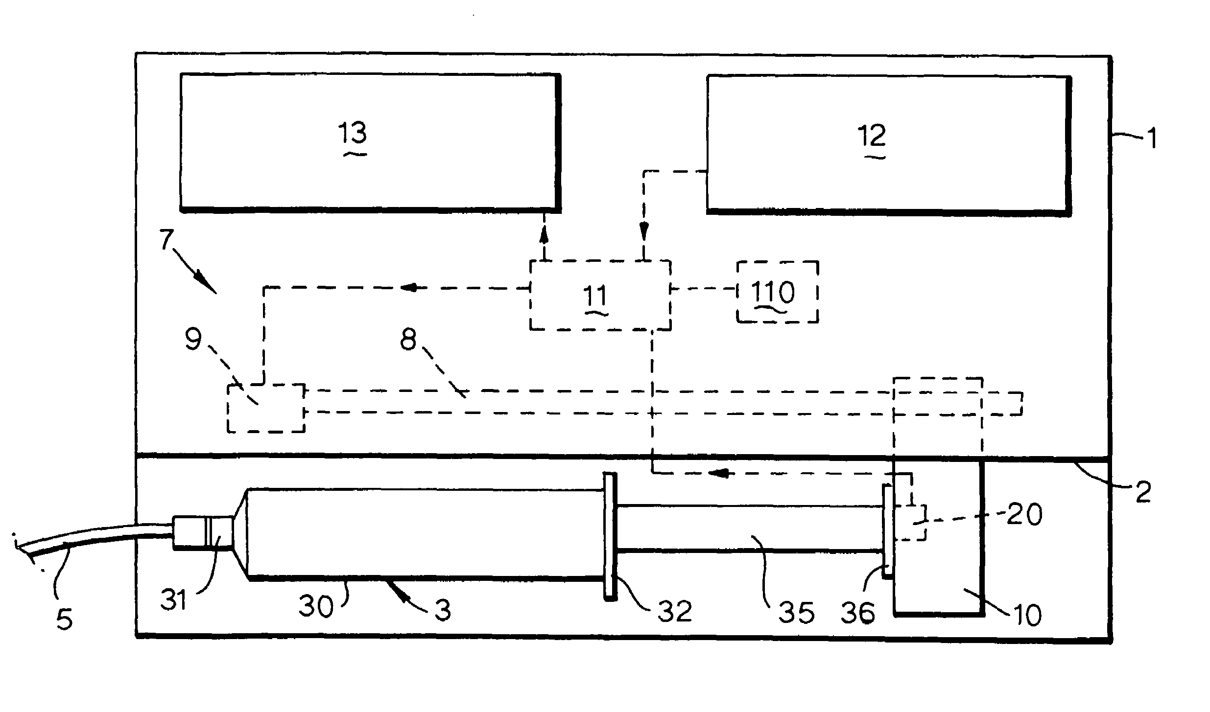
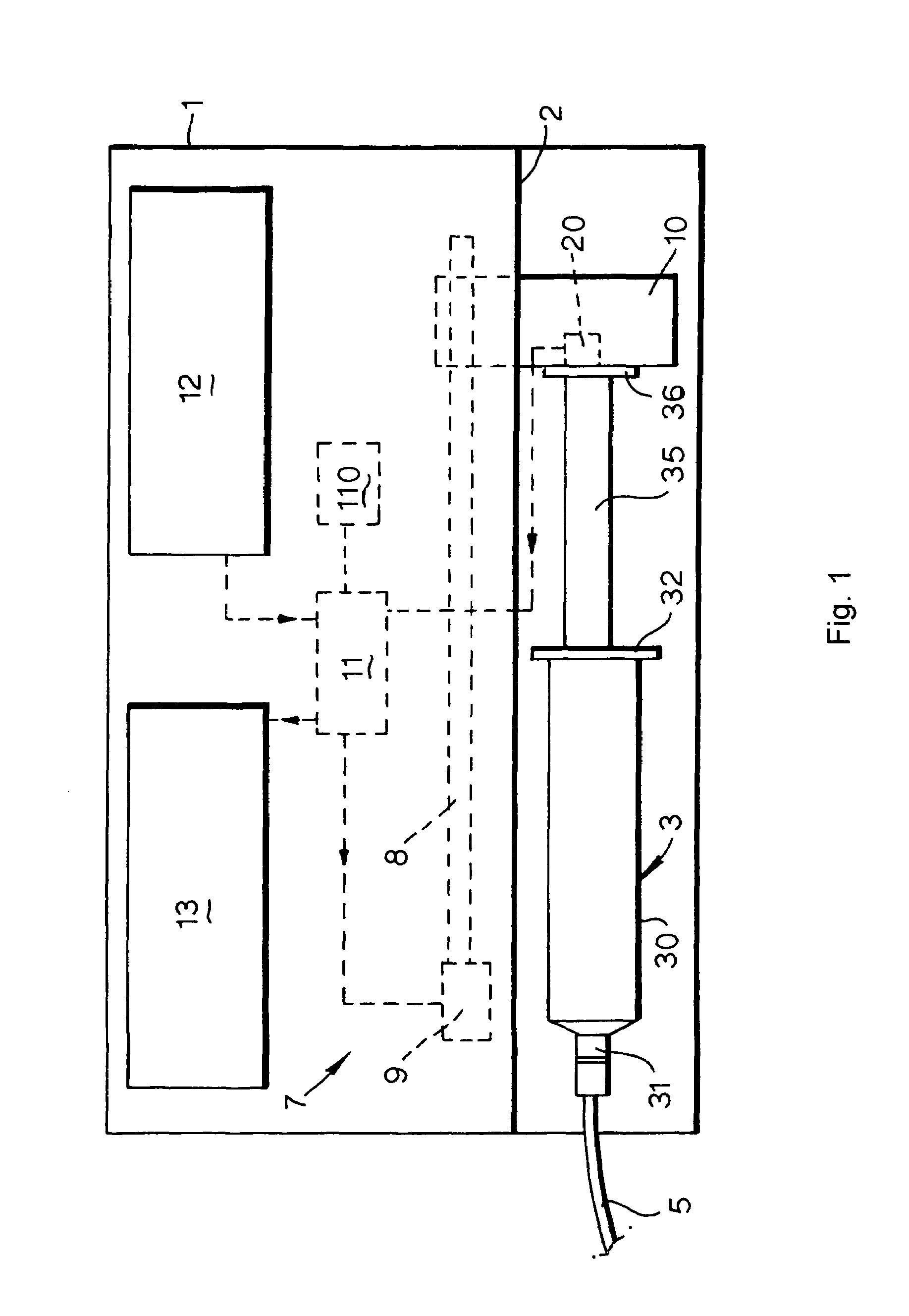
[0012]The pump includes an outer housing 1 with a recess 2 on its front surface shaped to receive a syringe 3 of conventional kind. The syringe 3 has a cylindrical barrel 30 with an outlet or nose 31 at its forward end and a flange or ear 32 at its rear end. The nose 31 is connected to an infusion line 5 so that a medication liquid in the syringe 3 can be dispensed to a patient via the infusion line, by pushing in the plunger 35. The pump has a drive mechanism 7, including a lead screw 8 driven by an electric motor 9. A retainer mechanism 10 is movable along the lead screw as it rotates and engages the head 36 of the plunger 35, so as to move the plunger along the barrel 30. The motor 9 is driven by a control unit 11, which receives inputs from a keypad 12, or other user input means, and various sensors. The control unit 11 also provides an output to a display 13.

[0013]The plunger head retainer 10 includes a force sensor 20, as described in greater detail in GB2352637, which respond...


PUM


Abstract

A syringe pump has a motor rotating a leadscrew, which drives a plunger head retainer to push a plunger along the barrel of a syringe so as to dispense medication to a patient. A force sensor in the head retainer measures the force on the plunger to detect when there is an occlusion restricting flow of medication. When an excess force is detected an alarm is generated and the motor is reversed to reduce the force to about 10% of that at which the occlusion is detected. The occlusion can be removed with a reduced risk of a bolus of medication being dispensed after which the user restarts the pump so that the plunger is driven normally.

Description

BACKGROUND OF THE INVENTION[0001]This invention relates to syringe pumps.[0002]Syringe pumps are used to supply medication to a patient from a pre-filled syringe via an infusion line. The syringe pump applies a force to the plunger of the syringe to drive medication into the infusion line at a controlled rate. It is common to have some provision to detect occlusion to flow of liquid out of the pump, such as caused by kinked tubing, and to respond to this by stopping the pump and sounding an alarm. The occlusion may be detected by measuring the force exerted on the plunger head by the pump driver, to detect excessive force. As described in GB2352637, the plunger head retainer itself may include a force sensor. The excess force produced until the occlusion is detected is accommodated by deformation of the elastic components, such as the fluid tubing and the syringe plunger head. When the pump is stopped, therefore, the medication fluid upstream of the occlusion is subject to compressi...

Claims


Application Information

Patent Timeline
IPC IPC(8): A61M31/00A61M1/00A61M37/00A61M5/00A61M5/145A61M5/168
CPCA61M5/1456A61M2205/18A61M2005/16863A61M5/16854
Inventor TRIBE, ROBERT JAMESPICKLES, CHRIS
Owner SMITHS MEDICAL INT
Why Eureka
Try Eureka