Ultraviolet lamp

a technology of ultraviolet light and lamp body, which is applied in the direction of discharge tube/lamp details, discharge tube luminescnet screens, gas-filled discharge tubes, etc., can solve the problems of reducing the energy consumption of electrodes and the self-absorption rate of electric particles, so as to increase brightness and lifespan, the effect of starting more quickly

Inactive Publication Date: 2009-12-22
FABUTECH DEV
View PDF4 Cites 0 Cited by
  • Summary
  • Abstract
  • Description
  • Claims
  • Application Information

AI Technical Summary

Benefits of technology

[0008]The object of the present invention is to provide an UV lamp, which starts more quickly and has increased brightness and lifespan.
[0010]The lamp is long and thin, which allows the working voltage to be high while the current remains low. This decreases the energy consumption of the electrode and the self-absorption rate of the electric particles during gas discharge. The hollow conical electrode requires less heat than an electrode of the same mass and therefore allows the lamp to start more quickly and decreases the emission loss when the glow discharge is transformed to the arc discharge of the electrode. The surface area of the coiled wire electrode is larger than that of a common wire electrode of similar type. As such, the emission loading is evenly distributed on the emission surface. Unlike common UV lamps, the emission loading is changed from point emission to surface emission, thus decreasing the electron scattering and allowing the lamp to resist the fierce impact from positive ions. The lamp in an embodiment of the present invention is thereby more efficient, brighter, and longer lasting than prior art lamps.
[0011]The lamp in an embodiment of the present invention also has an ozone resistant layer covering the outer surface. This layer is made of nano-materials such as nano-TiO2, and while the lamp is on, the concentration of ozone is controlled, and meanwhile it can improve the efficiency of photocatalysis of the UV lamp and can improve its sterilizing ability. This element of an ozone resistant layer can improve the usefulness of the present invention in the photocatalysis field.

Problems solved by technology

This decreases the energy consumption of the electrode and the self-absorption rate of the electric particles during gas discharge.

Method used


Image

  • Ultraviolet lamp
  • Ultraviolet lamp

Examples


Embodiment Construction

[0017]The description above and below and the drawings of the present document focus on one or more currently preferred embodiments of the present invention and also describe some exemplary optional features and / or alternative embodiments. The description and drawings are for the purpose of illustration and not limitation. Those of ordinary skill in the art would recognize variations, modifications, and alternatives. Such variations, modifications, and alternatives are also within the scope of the present invention. Section titles are terse and are for convenience only.

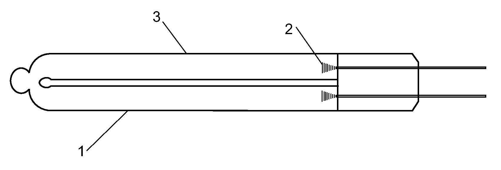
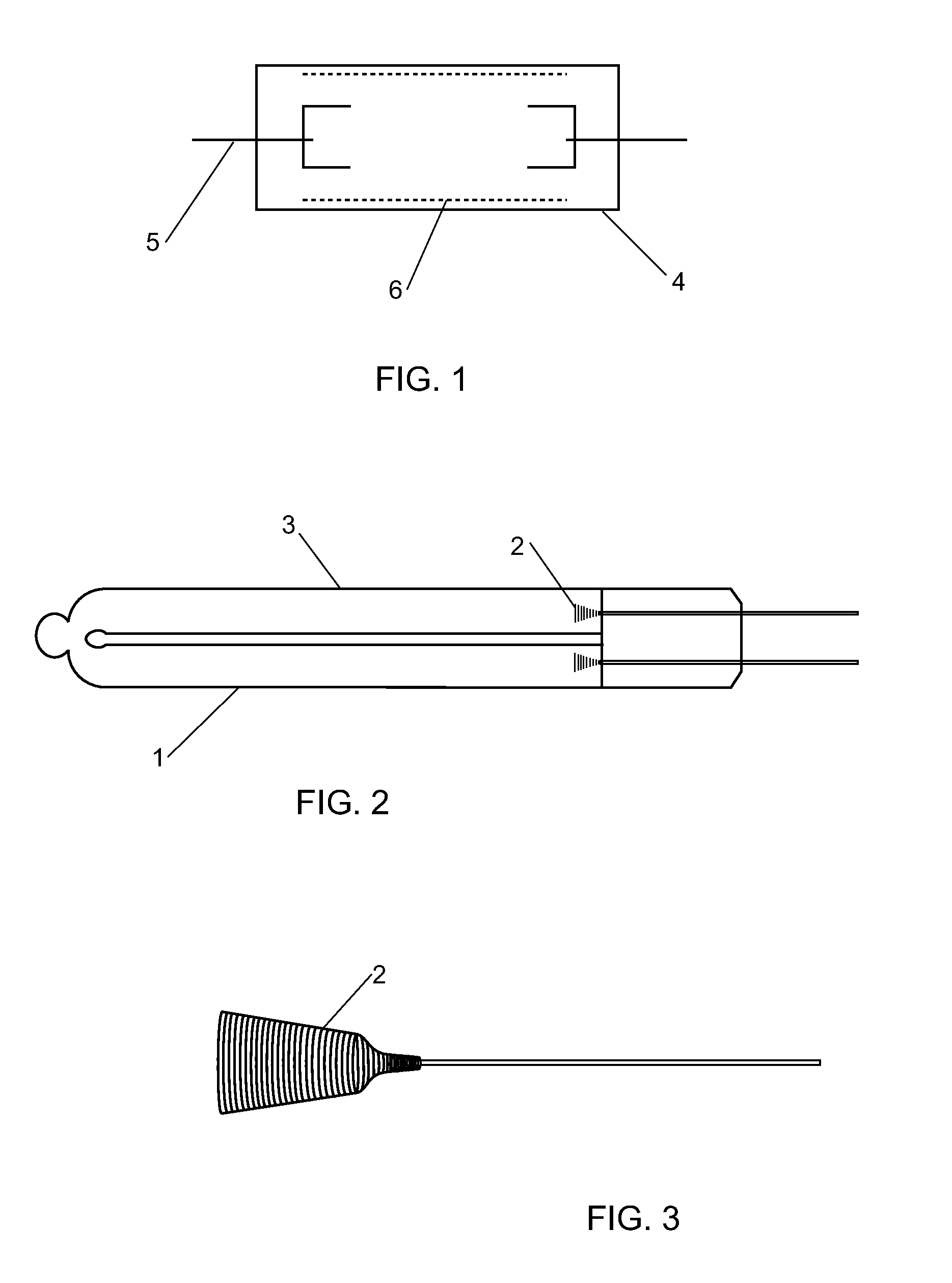
[0018]As shown in FIG. 1 and FIG. 2, according to an embodiment of the present invention, the lamp is a “U” shaped UV lamp having a first end and a second end, the lamp comprises a glass shell 1 and an electrode 2 positioned on each of the first end and second end of the lamp. The electrode 2 is a conically shaped coiled wire, in which the inner and bottom portion of the cone is hollow. In an embodiment of the present...


PUM


Abstract

The present invention relates to an ultraviolet lamp comprising a glass shell and an electrode fixed on one or more ends of the lamp, where each electrode is a coiled wire with a hollow conical shape. The hollowed conical structure of the electrode reduces the thermal capacity of the electrode as compared with other types of electrodes of the same mass, makes the lamp start quicker, and decreases the emission loss of the electrode when the glow discharge is transformed to an arc discharge. The lamp of the present invention has a wide electrode surface area, such that the loads on each point of the emissive surface are equally distributed, thus decreasing the electron scattering and dispersion, and allowing the lamp to resist the impact from positive ions. Due to the shape and structure of the electrode, the lamp of the present invention has increased efficiency and emitting ability, and allows for a longer lasting lamp.

Description

CROSS-REFERENCE TO RELATED APPLICATIONS[0001]This application claims foreign priority under 35 U.S.C. § 119 to Chinese Patent Application no. 200520045379.4, filed in the People's Republic of China on Sep. 28, 2005, the entire contents of which are hereby incorporated by reference.BACKGROUND OF THE INVENTION[0002]1. Field of the Invention[0003]The present invention relates to a gas-discharge lamp, in particular an ultraviolet (UV) lamp.[0004]2. Related Art[0005]There are generally two kinds of UV lamps: cold-cathode lamps and hot-cathode lamps. Hot-cathode UV lamps have the disadvantages of being bulky, having short life spans, being unstable, having low radiant intensity, and decreasing in radiant intensity over time because the coating of the filament oxidizes so quickly, evaporates and peels off. Cold-cathode UV lamps have a higher resistance to damage from shaking and longer life spans than hot-cathode UV lamps. Cold-cathode lamps have been used in many types of liquid crystal d...

Claims


Application Information

Patent Timeline
Patent Type & Authority Patents(United States)
IPC IPC(8): H01J17/16
CPCA61L2/10H01J61/35H01J61/0672
Inventor YANG, SHI GUANGWANG, JIAN CHENGCHAN, WAI MAN
Owner FABUTECH DEV
Why Eureka
Try Eureka