
Pool vacuum

a technology for vacuums and pools, applied in the direction of filtration separation, cleaning filter means, separation processes, etc., can solve the problem of limiting visibility, and achieve the effect of impaired visibility

Active Publication Date: 2009-12-29
WATERTECH
View PDF12 Cites 27 Cited by
  • Summary
  • Abstract
  • Description
  • Claims
  • Application Information

AI Technical Summary

Benefits of technology

[0006]An improved pool vacuum includes a filter cone and poppet valve combination which enables quick drainage of water which has passed through and been cleaned by the cleaner's filter. A charging circuit is provided with isolation so that the pool vacuum can be used in an electrolytic environment without battery drainage. A combination charger and hang bracket enables the pool vacuum to be stored in a vertical position to both drain and charge simultaneously. An interstitial open exhaust gap between a rear body and front nose-cone section provides a low pressure drop free exhaust area for an impeller. An optionally obstructed bottom gap portion helps to produce a net downward thrust to assist in using the vacuum in deep pools from a long pole structure. The same obstructed bottom gap, when used inverted, limits the impaired visibility caused by ripples on the surface of a shallow pool. Use of the pool vacuum with varying sizes of extensions between a handle and a handle bore fitting formed integral with a rear housing or with a very long pool pole is shown.

Problems solved by technology

The same obstructed bottom gap, when used inverted, limits the impaired visibility caused by ripples on the surface of a shallow pool.

Method used


Image

  • Pool vacuum
  • Pool vacuum
  • Pool vacuum

Examples


Embodiment Construction

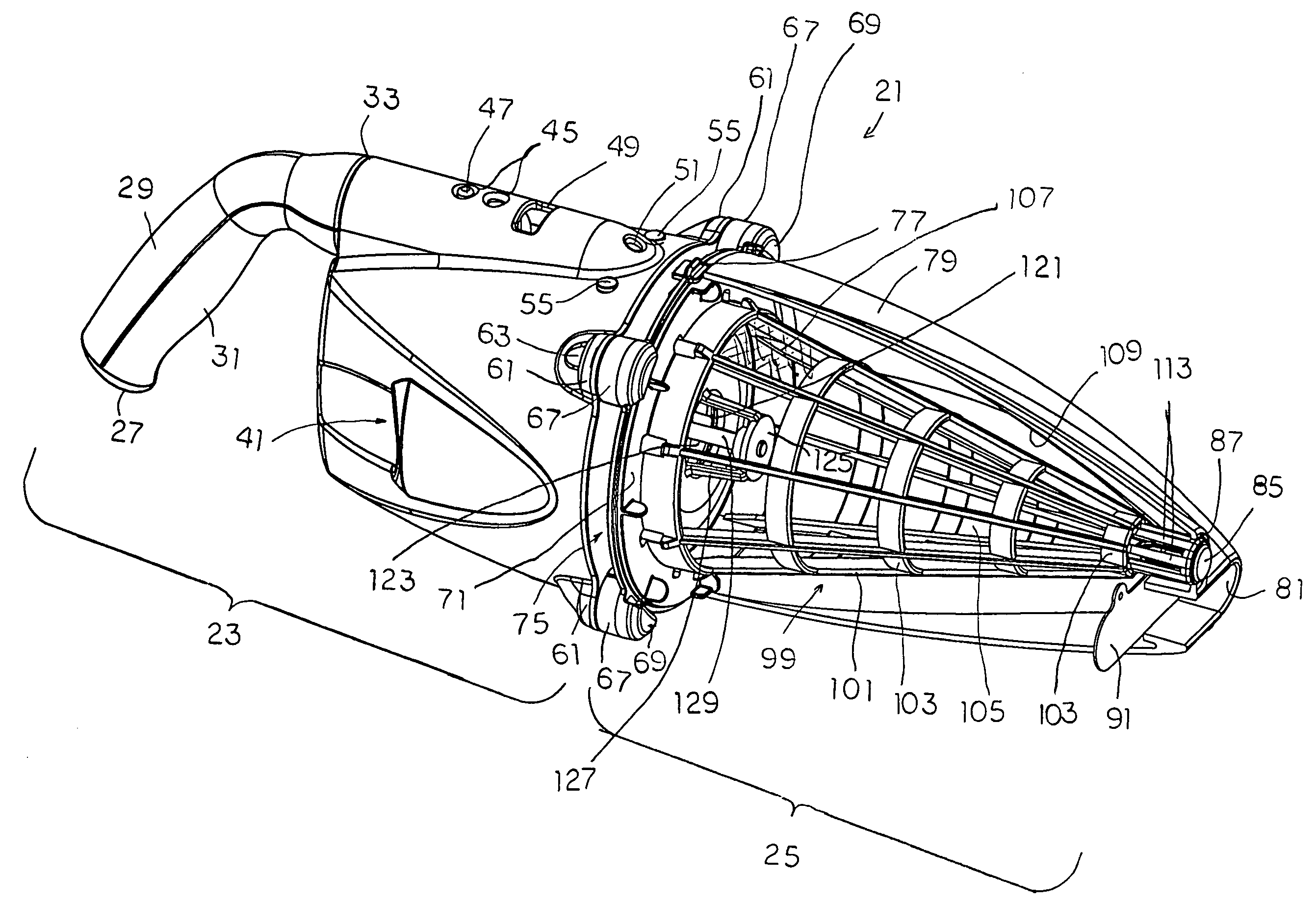
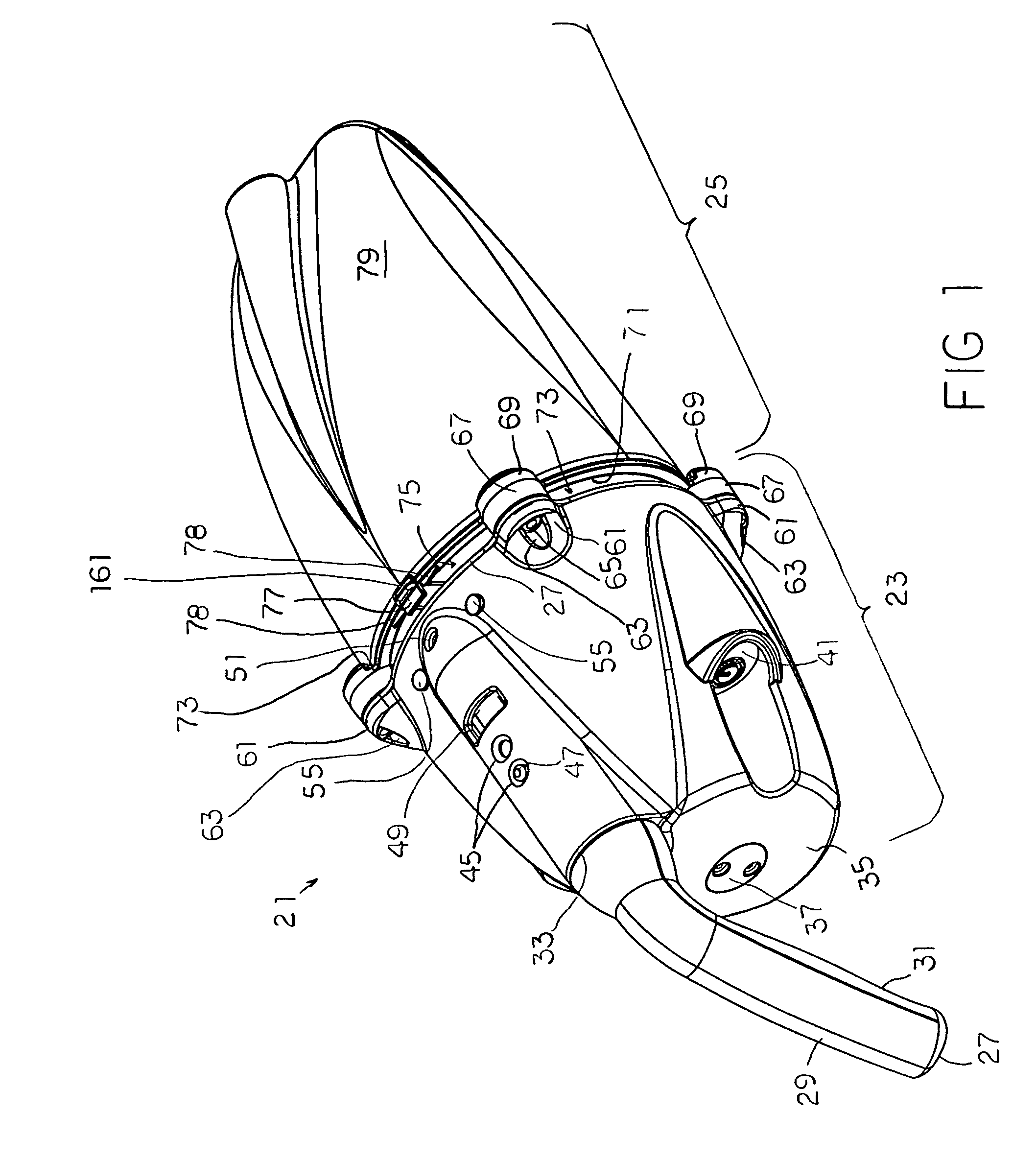
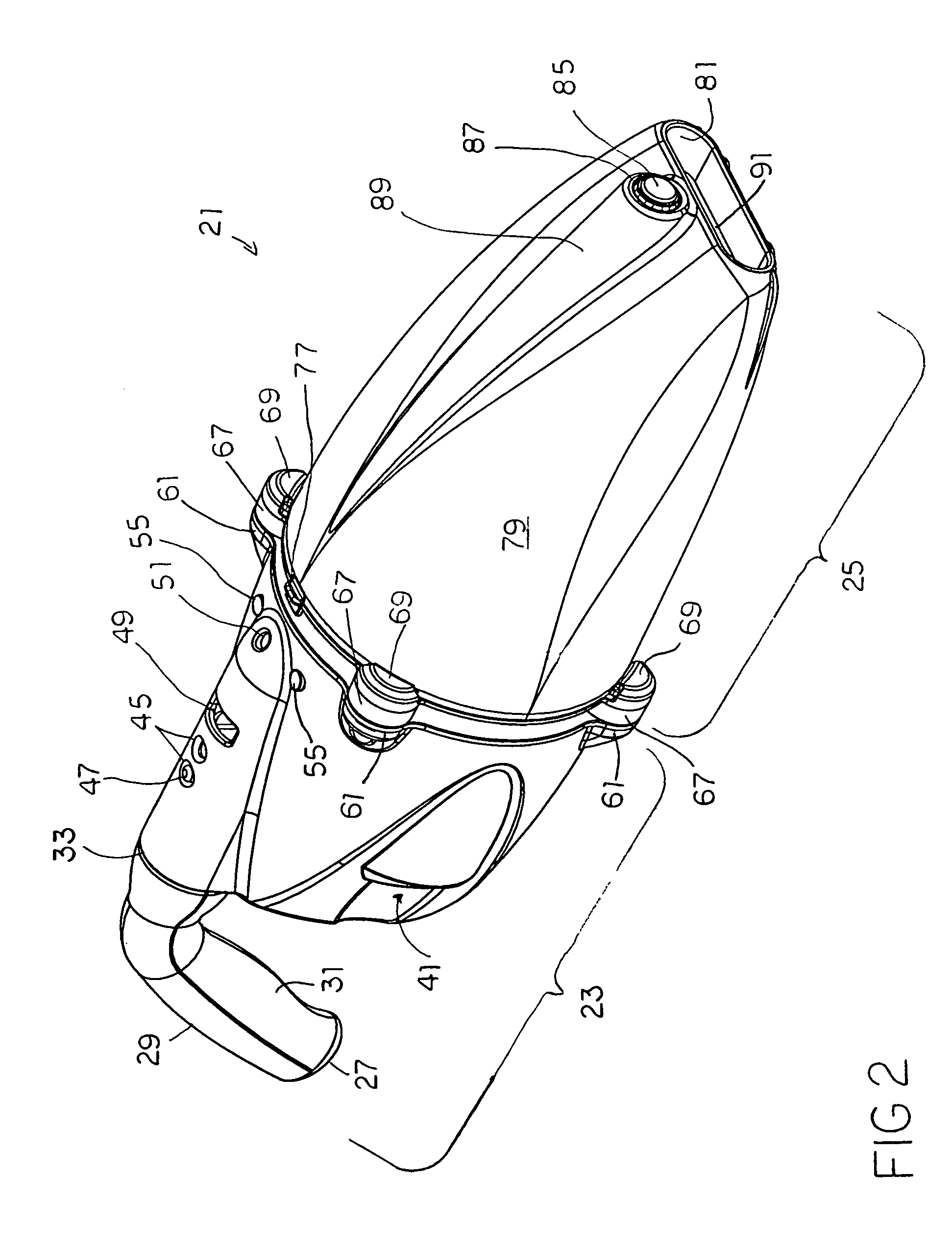
[0020]The description and operation of the pool vacuum of the invention will begin to be best described with reference to FIG. 1 which illustrates an exterior view of a pool vacuum 21 seen as having a rear body housing 23 and a nose-cone shaped front housing section 25. The construction of the pool vacuum 21 is somewhat modular with the rear body housing 23 including the mechanics and structural connections, while the nose-cone shaped front housing section 25 includes a filter cone, and water inlet. Water is expelled from a narrow space between the rear body housing 23 and a nose-cone shaped front housing section 25, as will be described.

[0021]At the left side of the rear body housing 23, a handle 27 may include an upper section 29 and a lower section 31 which may fit bayonet style into a handle bore fitting 33. The inclusion of handle bore fitting 33 as an integral part of the rear body housing 23 brings it closer to the centerline of the pool vacuum 21 with resulting ease of handl...


PUM

PropertyMeasurementUnit
vacuumaaaaaaaaaa
skeletal structureaaaaaaaaaa
areaaaaaaaaaaa

Abstract

An improved pool vacuum includes a filter cone and poppet valve combination which enables quick drainage of water which has passed through and been cleaned by the cleaner's filter. A charging circuit is provided with isolation so that the pool vacuum can be used in an electrolytic environment without battery drainage. A combination charger and hang bracket enables the pool vacuum to be stored in a vertical position to both drain and charge simultaneously. An interstitial open exhaust gap between a rear body and nose-cone shaped front section provides a low pressure drop free exhaust area for an impeller. An optionally obstructed bottom gap portion helps to produce a net downward thrust to assist in using the vacuum in deep pools from a long pole structure.

Description

FIELD OF THE INVENTION[0001]The present invention relates to an improvement in pool vacuums which facilitates deployment of the device, use of the device, and ease of stowage and cleaning.BACKGROUND OF THE INVENTION[0002]Conventional pool cleaning devices move water through a filter or trap system over a short distance from an inlet adjacent a surface to area to be cleaned, while expelling the water back into the pool environment. The placement of the pump within a vacuum unit eliminates the need to move water over a long distance or over a distance of vertical head. The ability to intake and expel the water from which the debris has been removed essentially eliminates energy which would have to overcome the pressure head. Thus only enough force is needed to move the water kinetically fast enough to provide a “sweeping” operation and to overcome the pressure drop due to the filter is needed.[0003]However, placement of the drive motor in a submerged position means that the delivery o...

Claims


Application Information

Patent Timeline
Patent Type & Authority Patents(United States)
IPC IPC(8): E04H4/16
CPCE04H4/1636
Inventor MAH, PAT Y.KALOGROULIS, ALEXANDER JOSEPHWHITE, MATTHEW EDWARD
Owner WATERTECH
Learn More