LED lamp

a technology of led lamps and led lamps, applied in the field of led lamps, can solve the problems of degrading the quality of illumination, the operation of conventional led lamps has a problem of instability, and the temperature of led lamps rises quickly, and achieves the effect of intensively focused and intensively focused

Inactive Publication Date: 2009-12-29
FU ZHUN PRECISION IND SHENZHEN +1
View PDF12 Cites 114 Cited by
  • Summary
  • Abstract
  • Description
  • Claims
  • Application Information

AI Technical Summary

Benefits of technology

[0008]An LED lamp for lighting includes a lamp base, a first heat sink mounted on the lamp base, a plurality of second heat sinks attached to a periphery of the first heat sink and a plurality of LED modules respectively attached to outer walls the second heat sinks. The outer walls of the second heat sinks are slantwise in respective to a vertical direction, whereby light generated by the LED modules can be more intensively focused in a first direction when the second heat sinks are mounted to the first heat sink by a first orientation, or can be more intensively focused in a second direction when the second heat sinks are mounted to the first heat sink by a second orientation inverted from the first orientation. The lamp base defines a plurality of vents therein. The first heat sink includes a cylinder at a centre thereof. The cylinder has a through hole defined therein, which communicates with the vents and cooperates with the vents to form an air passage communicating with ambient air.

Problems solved by technology

An LED lamp generally requires a plurality of LEDs, and most of the LEDs are driven at the same time, which results in a quick rise in temperature of the LED lamp.
Since generally the LED lamps do not have heat dissipation devices with good heat dissipating efficiencies, operation of the conventional LED lamps has a problem of instability because of the rapid build up of heat.
Consequently, the light from the LED lamp often flickers, which degrades the quality of the illumination.
Furthermore, the LED lamp is used in a state of high temperature for a long time, whereby the life time thereof is consequently shortened.
It is difficult to alter the predetermined directions of the LEDs to enable the LED lamp to be used in a different condition of requirement.

Method used


Image

  • LED lamp
  • LED lamp
  • LED lamp

Examples


Embodiment Construction

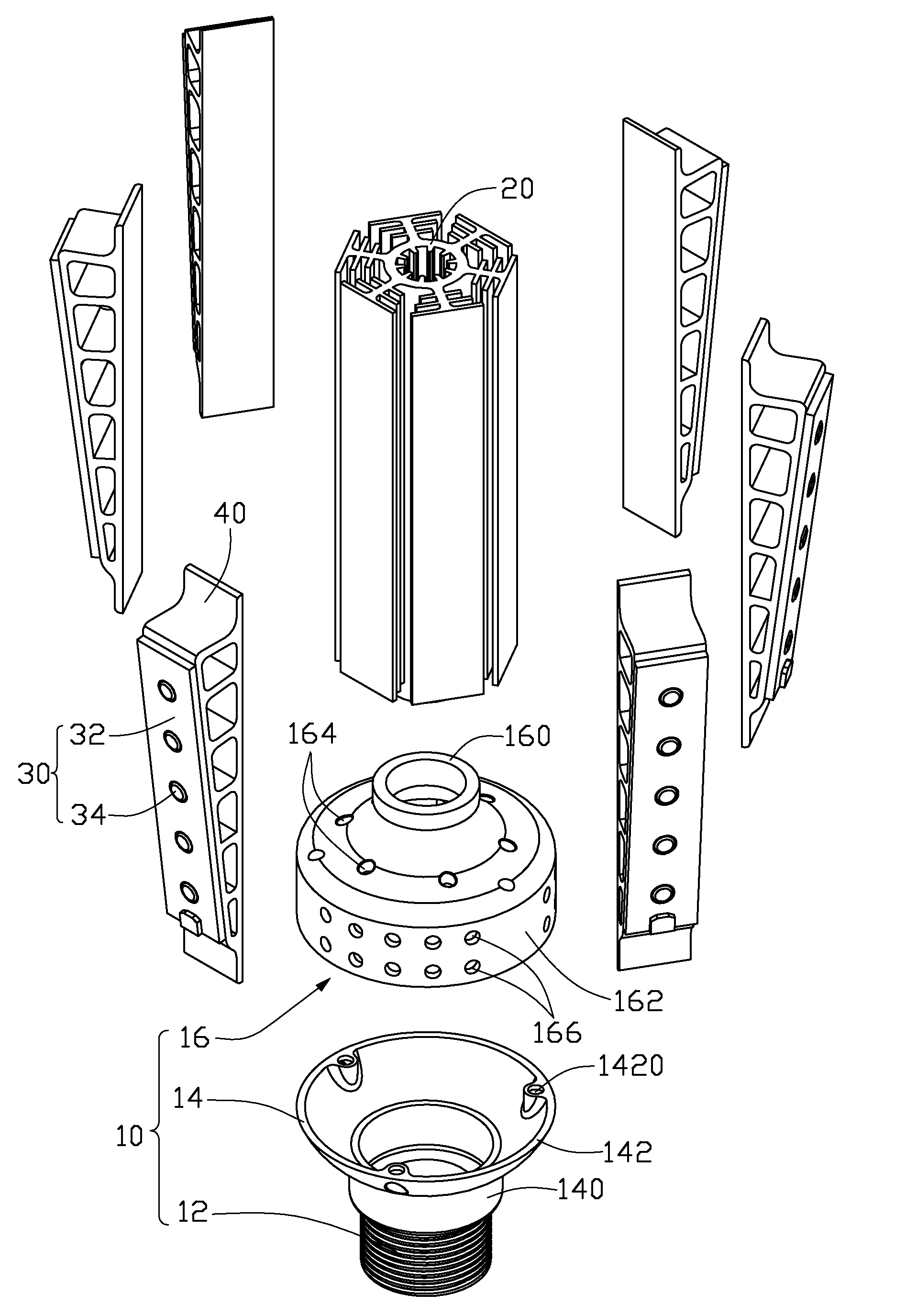
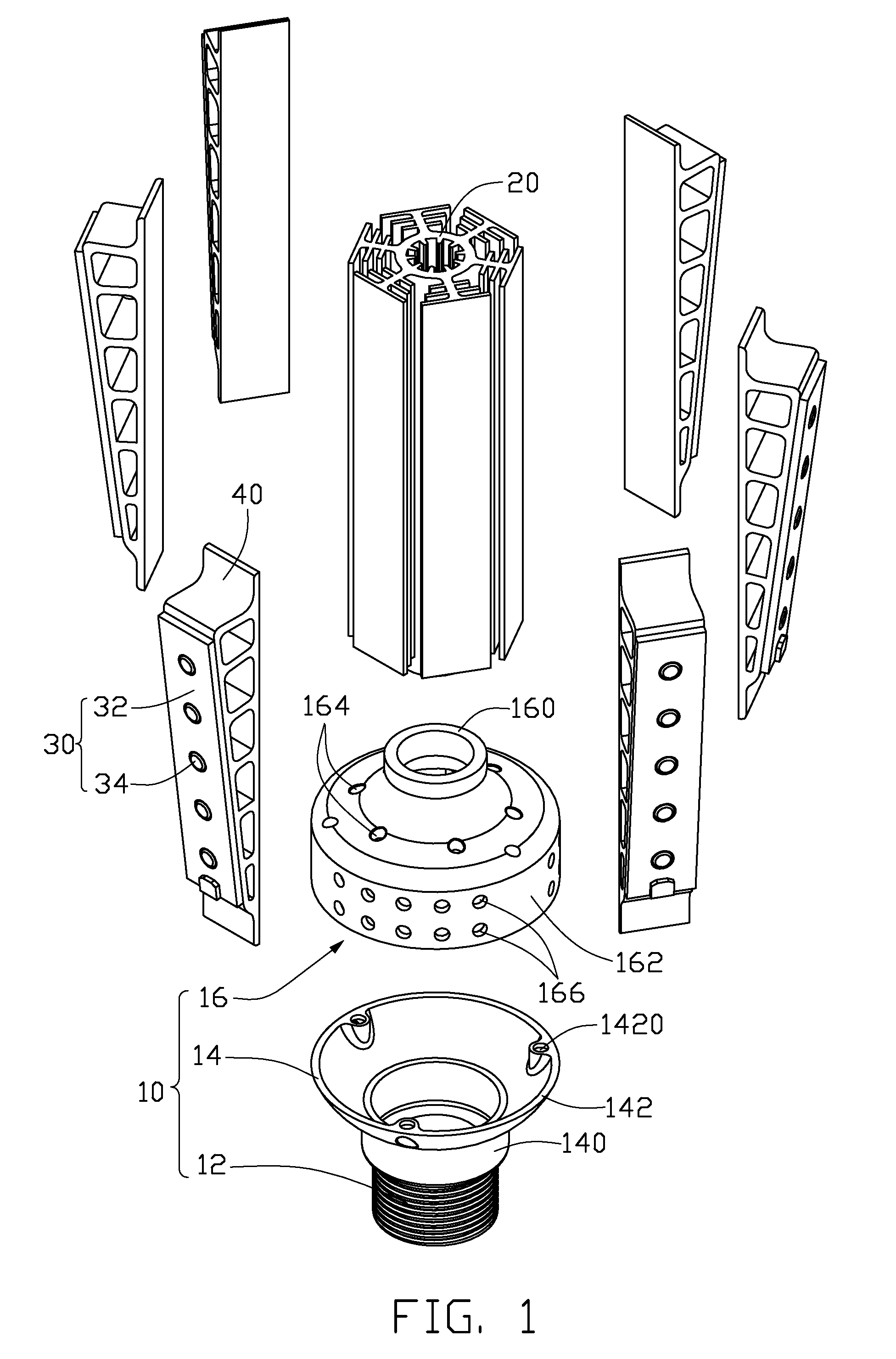
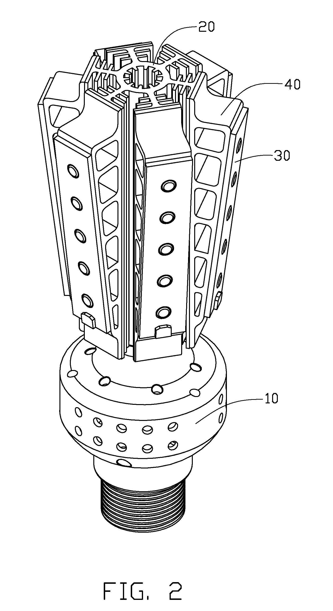
[0014]Referring to FIGS. 1-2, an LED lamp for a lighting purpose in accordance with a first preferred embodiment of the present invention is shown. The LED lamp comprises a lamp base 10, a first heat sink 20 mounted on the lamp base 10, a plurality of second heat sinks 40 attached to a periphery of the first heat sink 20 and a plurality of LED modules 30 thermally attached to the second heat sinks 40.

[0015]The lamp base 10 comprises a lamp holder 12, a first cover 14 connecting with the lamp holder 12 and a second cover 16 facing and engaging with the first cover 14. The lamp holder 12 has screw threads formed on a periphery thereof and has a standardized configuration for fitting in a standardized lamp socket (not shown). The first cover 14 comprises an annular joining portion 140 coupled with the lamp holder 12 and a first bowl-shaped body 142 extending upwardly from an upper edge of the joining portion 140. The first bowl-shaped body 142 has a caliber increasing upwardly. Three f...


PUM


Abstract

An LED lamp includes a lamp base (10), a first heat sink (20) mounted on the lamp base, a plurality of second heat sinks (40) attached to a periphery of the first heat sink and a plurality of LED modules (30) respectively attached to the second heat sinks. The lamp base defines a plurality of vents (166) therein. The first heat sink includes a cylinder (22) at a center thereof. The cylinder has a through hole (25) defined therein, which communicates with the vents and cooperates with the vents to form an air passage communicating with ambient air. A thickness of each of the second heat sinks is gradually varied along a height direction of the each of the second heat sinks.

Description

BACKGROUND OF THE INVENTION[0001]1. Field of the Invention[0002]The present invention relates to an LED lamp, and particularly to an LED lamp applying heat dissipation structures for dissipating heat from LEDs of the LED lamp.[0003]2. Description of Related Art[0004]An LED lamp is a type of solid-state lighting that utilizes light-emitting diodes (LEDs) as a source of illumination. An LED is a device for transferring electricity to light by using a theory that, if a current is made to flow in a forward direction through a junction comprising two different semiconductors, electrons and cavities are coupled at the junction region to generate a light beam. The LED has an advantage that it is resistant to shock, and has an almost eternal lifetime under a specific condition; thus, the LED lamp is intended to be a cost-effective yet high quality replacement for incandescent and fluorescent lamps.[0005]An LED lamp generally requires a plurality of LEDs, and most of the LEDs are driven at t...

Claims


Application Information

Patent Timeline
Patent Type & Authority Patents(United States)
IPC IPC(8): F21V29/00
CPCF21K9/135F21V29/004F21V29/83F21V29/75F21V29/76F21V29/77F21S2/005F21Y2101/02F21Y2103/003F21Y2111/007F21Y2111/005F21K9/232F21Y2103/10F21Y2115/10F21Y2107/30F21Y2107/40F21V29/74
Inventor ZHENG, SHI-SONGHE, LI
Owner FU ZHUN PRECISION IND SHENZHEN
Why Eureka
Try Eureka