Exhaust gas purification apparatus and exhaust gas purification method for internal combustion engine

a technology of exhaust gas purification apparatus and internal combustion engine, which is applied in the direction of machines/engines, electrical control, separation processes, etc., can solve the problems of inability to perform regeneration processing, sulfur poisoning recovery processing, etc., and the flow rate of exhaust gas flowing into the respective catalysts might not be regulated in a suitable manner, so as to achieve substantially uniform pm collection of the plurality of catalysts

Inactive Publication Date: 2010-01-05
TOYOTA JIDOSHA KK
View PDF29 Cites 25 Cited by
  • Summary
  • Abstract
  • Description
  • Claims
  • Application Information

AI Technical Summary

Benefits of technology

[0010]Accordingly, the object of the present invention is that in an exhaust gas purification apparatus for an internal combustion engine in which an independent exhaust passage is provided for each cylinder group with a catalyst having a NOx trapping ability and a PM trapping ability being arranged in each exhaust passage, so that the flow rates of exhaust gases flowing into the respective catalysts can be controlled independently from each other, thereby making it possible to perform the regeneration processing, the sulfur poisoning recovery processing, etc., of the catalysts in a suitable manner.
[0059]In addition, when the exhaust gas of the internal combustion engine flows in series through the plurality of catalysts during the cold operation of the internal combustion engine, all catalysts can be warmed by a great amount of the exhaust gas, so it becomes possible to make uniform the amounts of PM collections of all the catalysts while activating all the catalysts without delay.

Problems solved by technology

In case where an independent exhaust passage is provided for each cylinder group with a catalyst having a NOx trapping ability and a PM trapping ability being arranged in each exhaust passage, as in a V-type internal combustion engine, it is difficult to regulate the flow rates of the exhaust gases flowing into the respective catalysts independently from each other.
Therefore, regeneration processing, sulfur poisoning recovery processing, etc., of the catalysts might not be able to be performed in a suitable manner.

Method used


Image

  • Exhaust gas purification apparatus and exhaust gas purification method for internal combustion engine
  • Exhaust gas purification apparatus and exhaust gas purification method for internal combustion engine
  • Exhaust gas purification apparatus and exhaust gas purification method for internal combustion engine

Examples


first embodiment

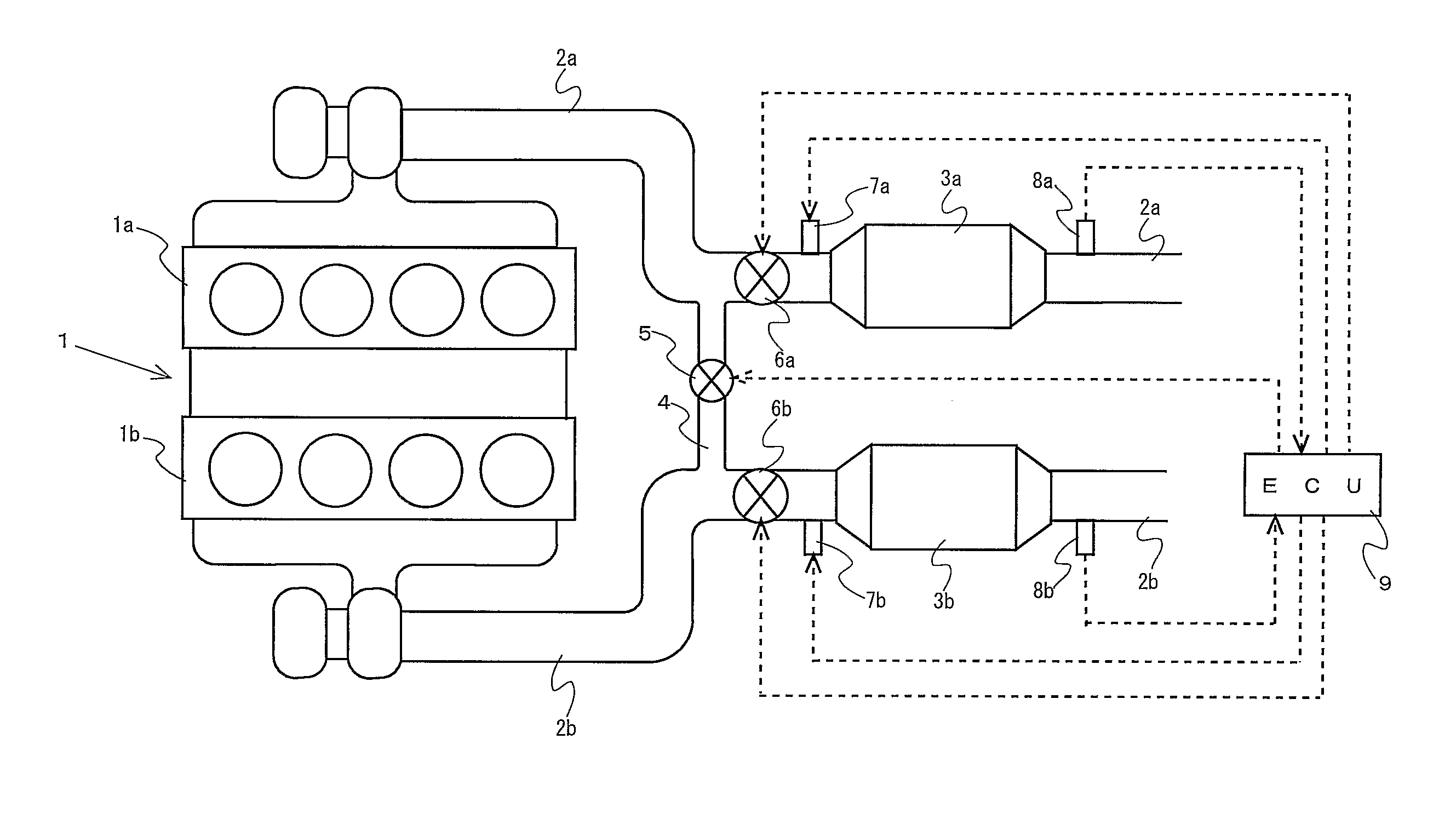
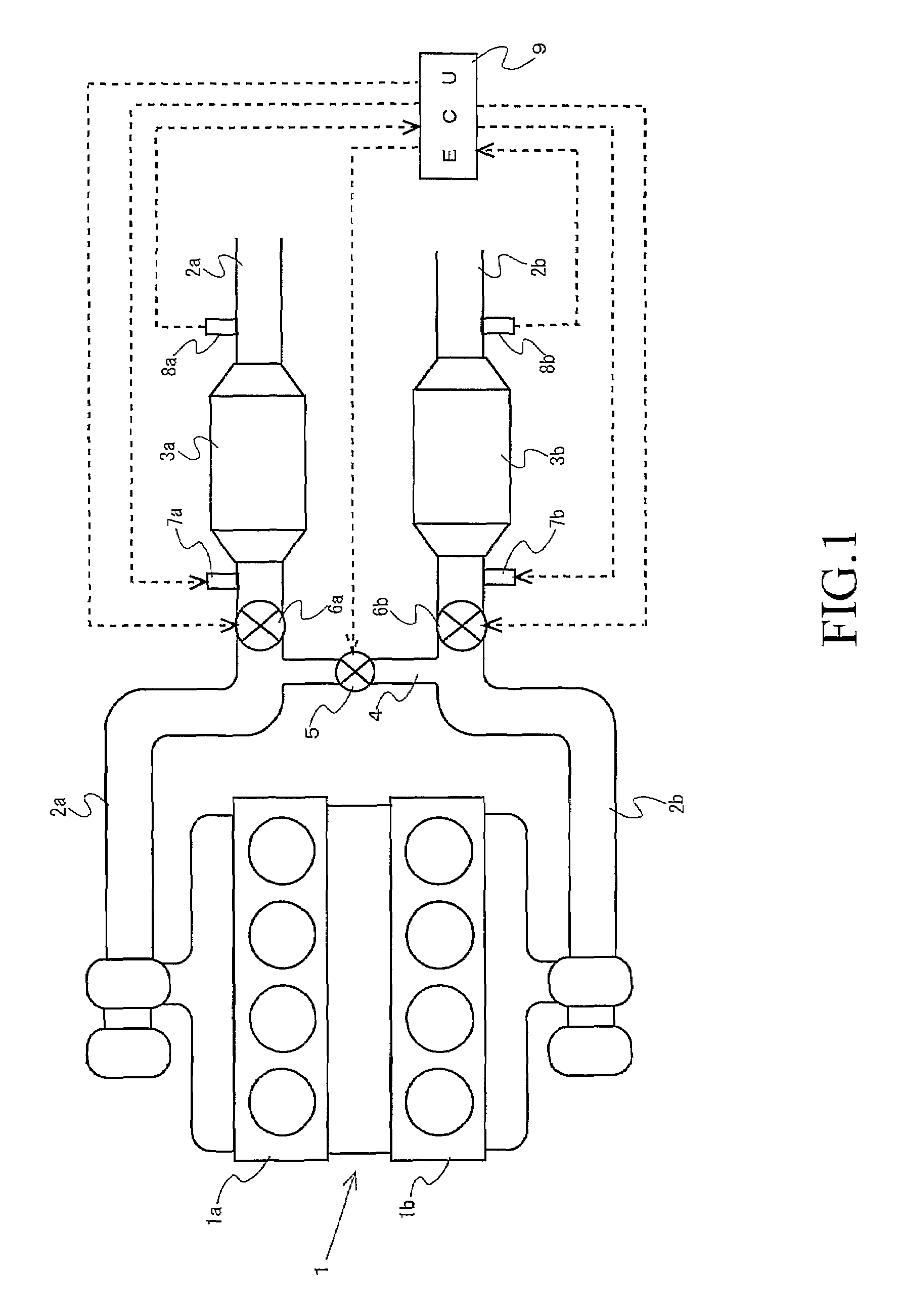
[0078]First of all, a first embodiment of the present invention will be described based on FIGS. 1 through 3. FIG. 1 is a view that shows the schematic construction of an internal combustion engine to which the present invention is applied. The internal combustion engine, generally designated at 1 in FIG. 1, is a compression-ignition type internal combustion engine (e.g., diesel engine) in which a first cylinder group (first bank) 1a and a second cylinder group (second bank) 1b are arranged in a V shape.

[0079]A first exhaust passage 2a and a second exhaust passage 2b are connected with the first and second banks 1a, 1b, respectively. A first NOx storage and reduction type catalyst 3a and a second NOx storage and reduction type catalyst 3b are arranged in the first and second exhaust passages 2a, 2b, respectively. Each of the first and second NOx storage and reduction type catalysts 3a, 3b is a catalytic converter in which an NOx storage and reduction type catalyst is carried or supp...

second embodiment

[0131]Now, reference will be made to a second embodiment of the present invention based on FIGS. 4 through 7. Here, those portions of the construction of this embodiment which are different from those of the above-mentioned first embodiment will be described while omitting an explanation about similar construction portions.

[0132]FIG. 4 is a view that shows the schematic construction of an internal combustion engine to which the present invention is applied. In FIG. 4, instead of the first NOx storage and reduction type catalyst 3a and the second NOx storage and reduction type catalyst 3b, a first filter 30a and a second filter 30b are arranged in the first exhaust passage 2a and the second exhaust passage 2b, respectively.

[0133]Each of the first filter 30a and the second filter 30b is a particulate filter that serves to capture or collect particulate matter (PM) in the exhaust gas. Also, each of the first filter 30a and the second filter 30b is provided with a catalyst having oxidiz...

third embodiment

[0203]Now, reference will be made to a third embodiment of the present invention based on FIGS. 8 through 10. Here, those portions of the construction of this embodiment which are different from those of the above-mentioned second embodiment will be described while omitting an explanation about similar construction portions.

[0204]FIG. 8 is a view that shows the schematic construction of an exhaust system of an internal combustion engine to which a third embodiment of the present invention is applied. In FIG. 8, a first flow rate regulation valve 6a is arranged in a first exhaust passage 2a at a location downstream of a first filter 30a, and a second flow rate regulation valve 6b is arranged in a second exhaust passage 2b at a location downstream a second filter 30b.

[0205]A first cutoff valve 20a is arranged in the first exhaust passage 2a at a location downstream of its connecting portion with an upstream side communication passage 4 and upstream of the first filter 30a. A second c...


PUM


Abstract

In an exhaust gas purification apparatus for an internal combustion engine (1) equipped with independent exhaust passages (2a, 2b) provided one for each cylinder group (1a, 1b) with a catalyst (3a, 3b) having a NOx trapping ability being arranged in each exhaust passage, the present invention is intended to provide a technique that can independently control the flow rates of exhaust gases flowing into the respective catalysts. To this end, the exhaust gas purification apparatus according to the present invention provides a communication passage (4) connecting mutually portions of said exhaust passages (2a, 2b) at upstream of said catalysts (3a, 3b), an upstream side switching valve (5) openning and closing said upstream side communication passage (4), a plurality of flow rate regulation valves (6a, 6b) being arranged at downstream of connecting portions of said exhaust passages with said upstream side communication passage, respectively, and a control section (9) controlling said upstream side switching valve (5) and said respective flow rate regulation valves (6a, 6b) in accordance with the states of said respective catalysts (3a, 3b). When the NOx trapping ability of one of the plurality of catalysts (3a, 3b) is regenerated, the control section (9) opens the upstream side switching valve (5), fully closes one flow rate regulation valve (6a, 6b) in one of the exhaust passages (2a, 2b) in which the one catalyst (3a, 3b) is arranged, and operates a reducing agent addition valve (7a, 7b) in such a manner that the reducing agent arrives at the one catalyst (3a, 3b) when the actual degree of opening of the one flow rate regulation valve (6a, 6b) becomes fully closed.

Description

TECHNICAL FIELD[0001]The present invention relates to an exhaust purification apparatus for an internal combustion engine in which a plurality of NOx traps are arranged in parallel with one another in an exhaust system of the internal combustion engine.BACKGROUND ART[0002]As an exhaust gas purification apparatus for an internal combustion engine, Japanese patent No. 2727906 discloses technique in which an exhaust passage of the internal combustion engine is bifurcated into two branch passages at its intermediate portion, and a NOx trap is arranged in each branch passage, so that the amounts or flow rates of exhaust gas flowing into these NOx traps can be alternately decreased to regenerate the NOx trapping abilities of the NOx traps.[0003]In the specification of U.S. Pat. No. 5,956,949, there is disclosed a technique that includes two exhaust passages connected with the respective banks of cylinders of a V-type internal combustion engine, and a catalyst arranged in each of the exhau...

Claims


Application Information

Patent Timeline
Patent Type & Authority Patents(United States)
IPC IPC(8): F01N3/00
CPCB01D53/9431B01D53/9495F01N3/0233F01N3/0842F01N3/0878F01N3/2093F01N13/011F02D41/028F02D41/1443F01N13/009F01N13/107F02B37/00Y02T10/24Y02T10/12
Inventor YOSHIZAKI, KOUJIOGISO, MAKOTO
Owner TOYOTA JIDOSHA KK
Why Eureka
Try Eureka