Coding method, decoding method, coding apparatus, decoding apparatus, image processing system, coding program, and decoding program

Active Publication Date: 2010-01-05
NTT DOCOMO INC
View PDF22 Cites 88 Cited by
  • Summary
  • Abstract
  • Description
  • Claims
  • Application Information

AI Technical Summary

Benefits of technology

[0051]Namely, it is possible to employ a configuration comprising an assignment information decoding step of decoding motion vector assignment information indicating which of one or more motion vectors decoded in each unit of the first block, a motion vector assigned in units of second blocks obtained by sub-dividing each of first blocks resulting from division of a frame of the moving picture corresponds to; and a motion compensation step of performing motion compensation using motion vectors specified in units of the second blocks on the basis of the motion vector assignment information and generating a predicted image; and a residual signal decoding step of decoding a predictive residual signal of the motion compensated prediction obtained by coding processing in block units of the same size as that of the second blocks. In this case, the residual signal decoding step is to decode the predictive residual signal of motion compensated prediction obtained by the coding processing in block units of the same

Problems solved by technology

However, the method of preparing the many motion division patterns as inter prediction modes has the problem that more motion vector information needs to be transmitted with increase in the number of motion divisions, so as to result in increase of the overhead. FIG. 5 shows the volume of transmitted information necessary for each of

Method used


Image

  • Coding method, decoding method, coding apparatus, decoding apparatus, image processing system, coding program, and decoding program
  • Coding method, decoding method, coding apparatus, decoding apparatus, image processing system, coding program, and decoding program
  • Coding method, decoding method, coding apparatus, decoding apparatus, image processing system, coding program, and decoding program

Examples


Example

[0166]First, the first embodiment of the present invention will describe the video coding apparatus configured to implement coding in macroblock units, particularly, the video coding apparatus and decoding apparatus configured to perform the motion compensated prediction while assigning up to two motion vectors to sub-blocks obtained by dividing a macroblock in 4×4 pixel units.

[0167]The configurations and operations of the image coding and decoding apparatus based on the H.26L coding method to which the present invention is applied will be described below.

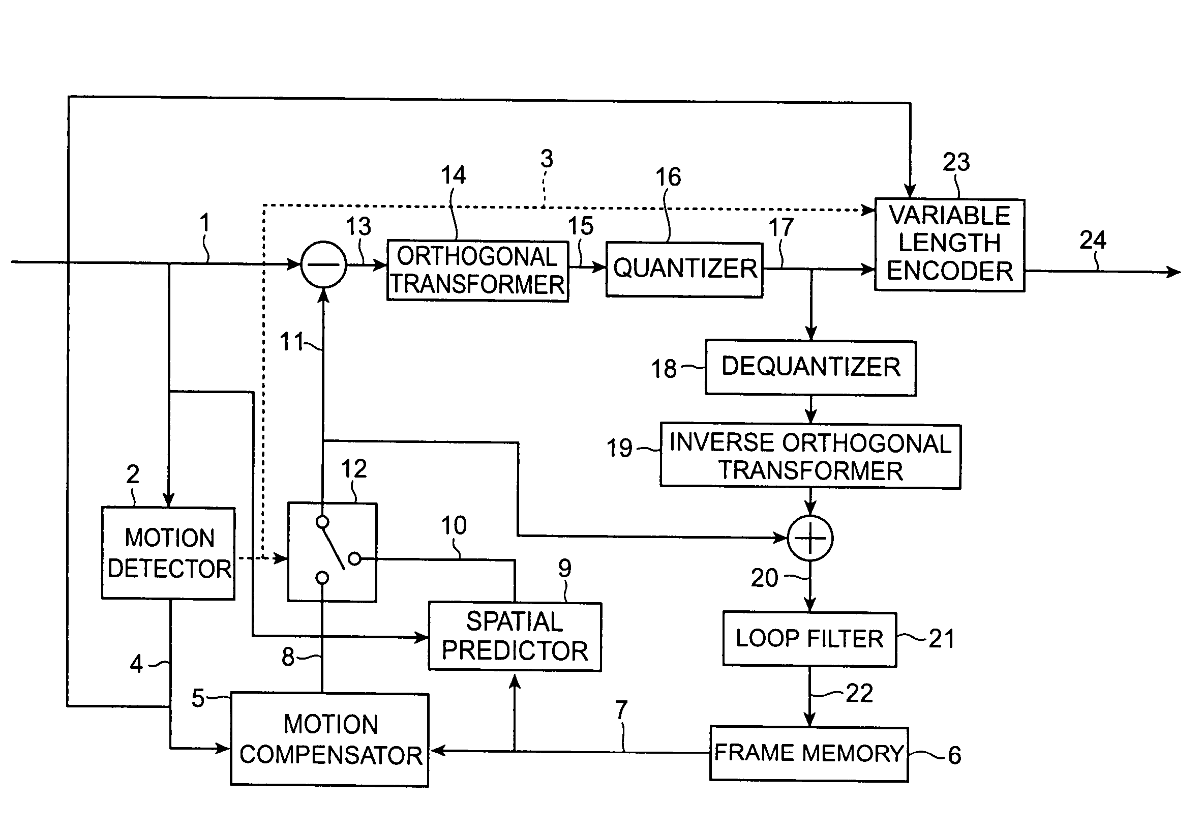
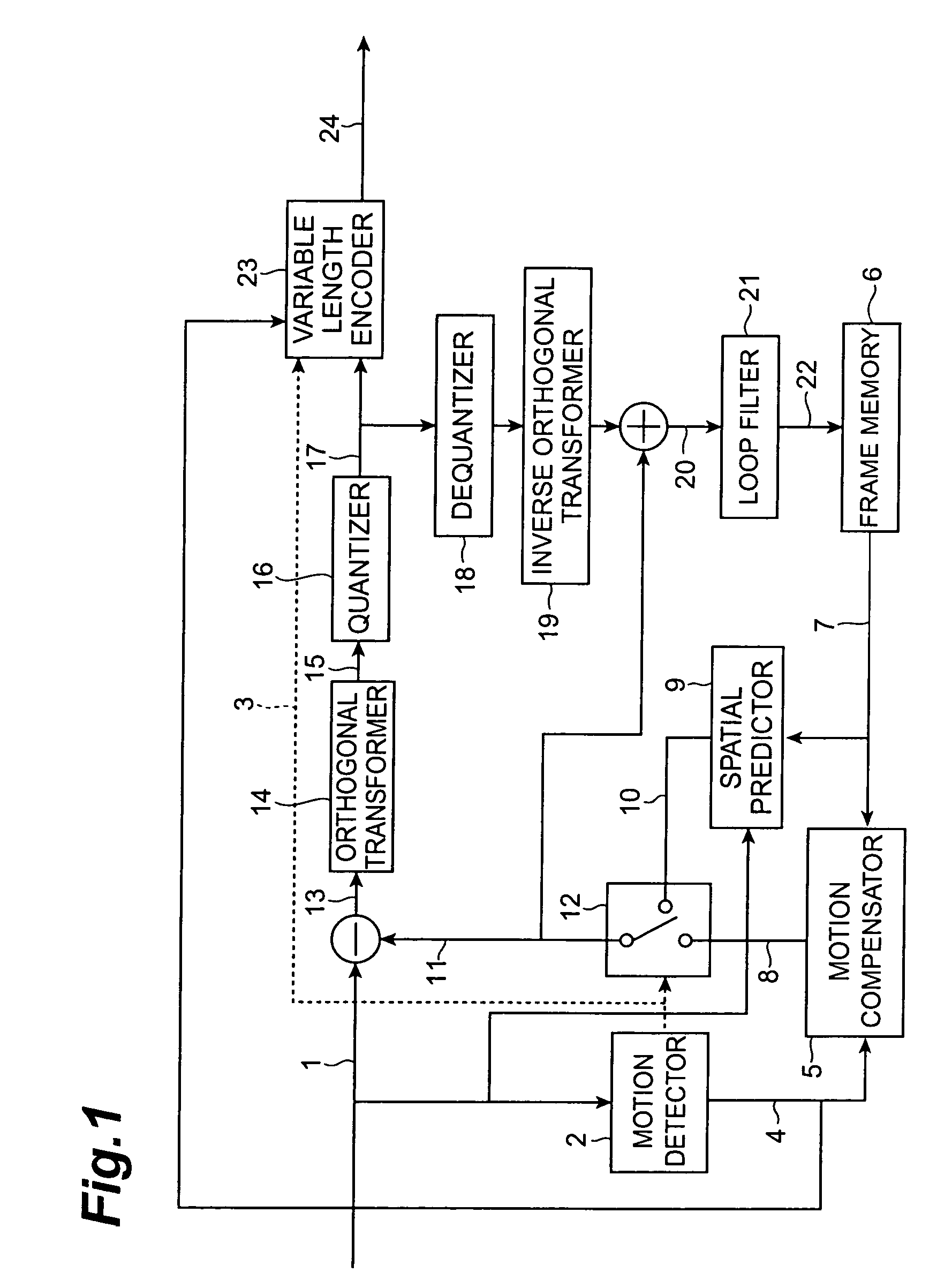
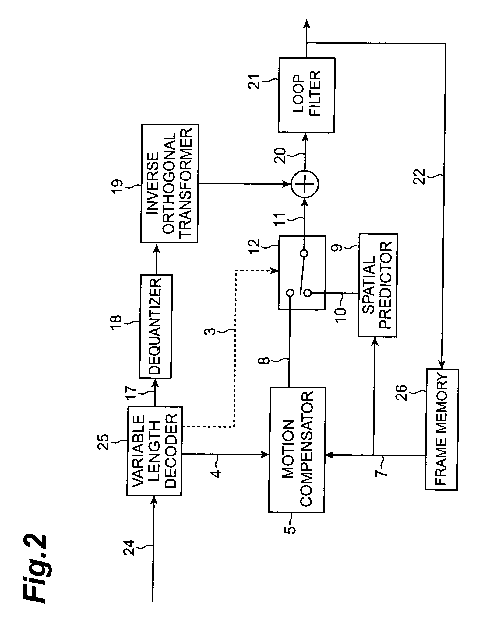
[0168]FIG. 1 shows the configuration of the coding apparatus and FIG. 2 the configuration of the decoding apparatus. In the coding apparatus of FIG. 1, information compression of video signal is implemented by reducing the redundancy present in the temporal direction by motion compensated inter prediction and further reducing the redundancy remaining in the spatial direction by orthogonal transform. FIGS. 3A and 3B provide illustra...

Example

[0233]The second embodiment will be described below. The present embodiment will describe the video coding apparatus configured to perform coding in macroblock units, particularly, the video coding apparatus and decoding apparatus configured to use up to two motion vectors per macroblock and to perform the motion compensated prediction while assigning the two motion vectors, in units of sub-blocks obtained by dividing a macroblock into 4×4 pixel units. The first embodiment described that the motion vectors were assigned in units of sub-blocks according to the fixed patterns, whereas the present embodiment will describe the coding apparatus and decoding apparatus configured to permit arbitrary designation of motion vector assignment to each sub-block.

[0234]The present embodiment can be described with the same members and operations except for differences in the definitions of the prediction mode 3 (particularly, the inter prediction modes) and the motion vector 4 in the compressed st...

Example

[0253]The third embodiment will be described below. The present embodiment will describe another coding method of the prediction mode 3 of FIG. 1 to indicate the arbitrary division pattern in the second embodiment. FIG. 21 shows the processing flow of the coding method in conjunction with the specific example used in FIG. 16A, and FIG. 22 are illustrations to explain the processing. First, S301 in FIG. 21 is to determine the prediction priority context as in the second embodiment. When the vertical prediction priority context is selected herein, change points are detected as locations of change where the motion vector assignment changes with respect to the lowermost sub-block line of macroblock A (S302). For example, in the case of macroblocks A, C of FIG. 22A, bold portions are detected as change points. This results in generating a binary map of FIG. 22B with each changing point assigned 1 and with each unchanging point assigned 0. This map is scanned with a predetermined scan tab...


PUM


Abstract

For the purpose of coding or decoding motion information in a picture with a small overhead, a coding method of performing compression coding of a moving picture by motion compensated prediction is configured to have a motion compensated prediction step (processing by motion detector 2, motion compensator 5, spatial predictor 9, etc.) of performing the motion compensated prediction while assigning one or more motion vectors (e.g., up to two motion vectors) in units of sub-blocks obtained by sub-dividing each of macroblocks resulting from division of each frame of the moving picture; and an assignment information coding step (processing by variable length encoder 23 and others) of outputting information about an assignment situation of the one or more motion vectors to the sub-blocks in a multiplexed form on a bitstream.

Description

TECHNICAL FIELD[0001]The present invention relates to a coding method, coding apparatus, and coding program of performing compression coding of a moving picture by motion compensated prediction, a decoding method, decoding apparatus, and decoding program of performing decompression and decoding of compressed moving picture data by motion compensated prediction, and an image processing system comprised of the coding apparatus and decoding apparatus.BACKGROUND ART[0002]The image coding and decoding method based on the H.26L coding method is known as a case example of the conventional video coding methods, which is described in International Standardization Working Document ITU-T SG16 VCEG-M81, “H.26L Test Model Long Term Number 7 (TML-7)” draft0 (http: / / standard.pictel.com / ftp / video-site / 0104—Aus / VCEG-M81d0.doc).[0003]In this H.26L video coding, many motion division patterns shown in FIG. 4A to FIG. 4G are prepared as inter prediction modes so as to enable elaborate motion compensatio...

Claims


Application Information

Patent Timeline
IPC IPC(8): H04N7/18H04N19/109H04N19/117H04N19/137
CPCH04N19/176H04N19/119H04N19/46H04N19/51H04N19/196H04N19/61H04N19/577H04N19/463H04N19/137H04N19/17H04N19/57H04N19/573H04N19/109H04N19/117
Inventor KATO, SADAATSUETOH, MINORUSEKIGUCHI, SHUNICHIYAMAGUCHI, HIROYUKIOGIRI, YASUHIROADACHI, SATORUKOBAYASHI, MITSURU
Owner NTT DOCOMO INC
Why Eureka
Try Eureka