Design tool and methodology for enterprise software applications

a software application and design tool technology, applied in the direction of instruments, symbolic schematics, cad techniques, etc., can solve the problem of not enough consideration of the requirements of the software entity itself, and achieve the effect of facilitating the creation of a simulation model

Active Publication Date: 2010-01-05
KHODABANDEHLOO PAYMAN +1
View PDF28 Cites 153 Cited by
  • Summary
  • Abstract
  • Description
  • Claims
  • Application Information

AI Technical Summary

Benefits of technology

[0052]Once the visual description is built, the disclosed computing system allows the team to build and maintain consensus and certainty about the requirements, design and specification of that conceptual construct. This visual description is malleable and allows the impact of any change to be visible and demonstrable throughout the construct, from the smallest low level code detail to an actual task and the resource performing that task. The visual model of the complex system presented in the computing system accomplishes these goals without cognitively overwhelming the user.
[0065]In another aspect, the subject disclosure is a server for facilitating a creation of a simulation model for a complex enterprise software solution, wherein the server communicates with clients via a distributed computing network. The server includes (a) a memory storing an instruction set and data related to the simulation model, and (b) a processor for running the instruction set, the processor being in communication with the memory and the distributed computing network. The processor is operative to: (i) present a text canvas that includes a table to represent a solution to a request for software code that addresses a problem such that an editor is able to modify text of the table; (ii) present an interactive schematic canvas that includes expandable icons arranged on a circle to represent the solution such that a system architect is able to navigate and modify the expandable icons; (iii) present a data canvas that includes a branching structure to represent the solution such that a data analyst is able to navigate and modify the branching structure; and (iv) present a user interface canvas that uses graphics to represent the solution such that a user interface designer is able to modify the graphics, wherein the canvases are related to form a conceptual construct such that a modification to one canvas is promulgated to at least one other canvas within the conceptual construct so that the editor, system architect, data analyst and user interface designer effectively communicate together while using the corresponding canvas. Preferably, the graphics of the user interface canvas include storyboards, promulgation includes the step of coupling a modification to the conceptual construct, and modifications can be decoupled.

Problems solved by technology

When evaluating the requirements for a software project, considering the requirements of the software entity itself is not enough.

Method used


Image

  • Design tool and methodology for enterprise software applications
  • Design tool and methodology for enterprise software applications
  • Design tool and methodology for enterprise software applications

Examples


Embodiment Construction

[0093]The present invention overcomes many of the prior art problems associated with building complex, multi-layered structures. The advantages, and other features of the systems and methods disclosed herein, will become more readily apparent to those having ordinary skill in the art from the following detailed description of certain preferred embodiments taken in conjunction with the drawings which set forth representative embodiments of the present invention and wherein like reference numerals identify similar structural elements.

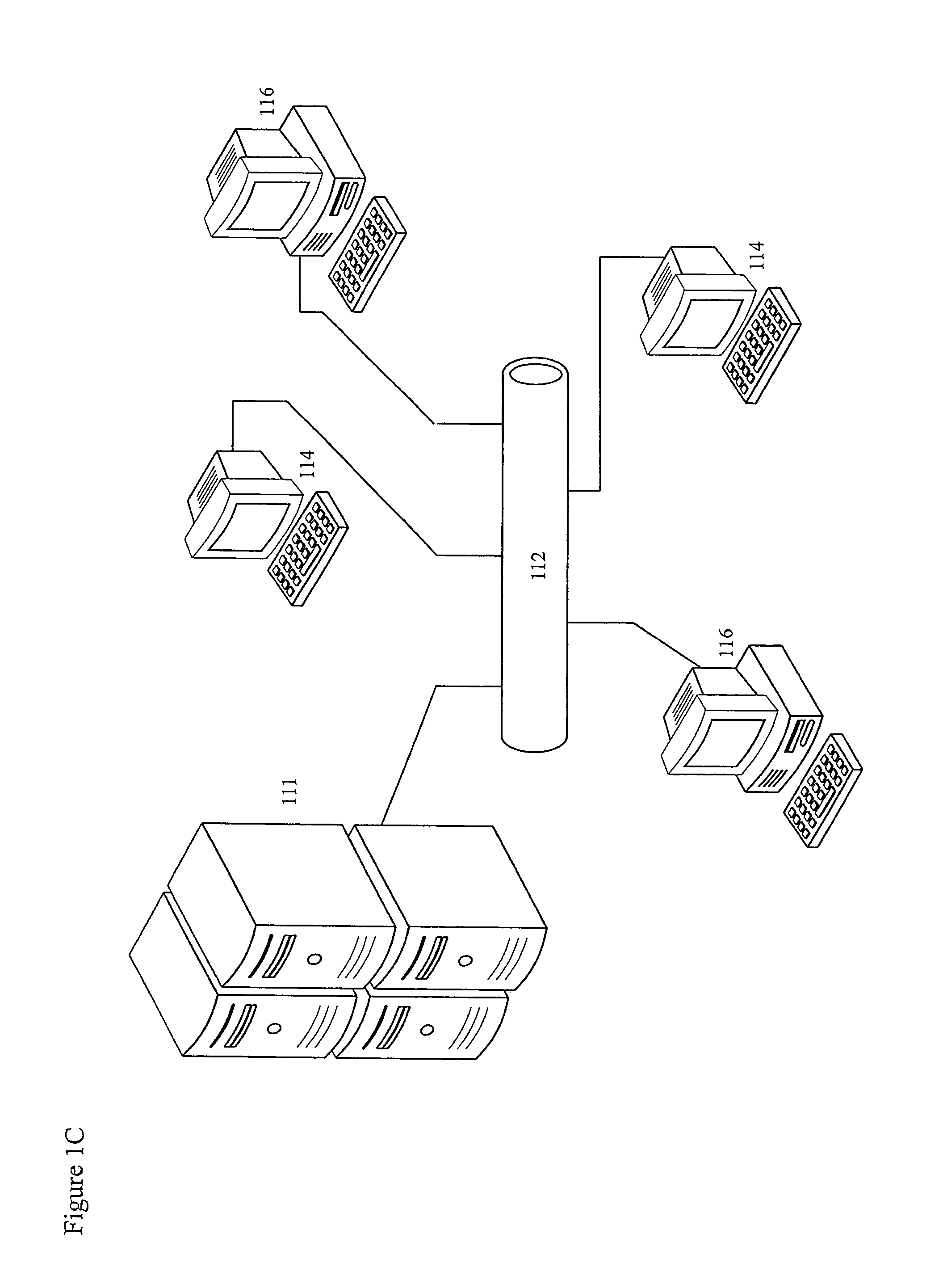
[0094]Referring now to the FIG. 1C, there is shown in FIG. 1C a block diagram of an computing system 100 embodying and implementing the methodology of the present disclosure. The computing system 100 connects users (business analysts, programmers, end users, managers and the like) via a network 112. The following discussion describes the structure of such an computing system 100 but further discussion of the applications program and data modules that embo...


PUM


Abstract

A system for creating and viewing simulation models that are used for managing requirements and design specifications for complex systems. Users simultaneously collaborate on the description of a complex system such as an enterprise software project throughout its life cycle. User interfaces, designed to assist in the visualization of a particular form of knowledge, allow users to describe the complex system with simple interactive elements. Information in all perspectives is presented so that it is legible and discernable to a non-technical audience. Multi-dimensional data structures record all the resulting information, creating a simulation model of the complex system, and the tasks required for construction and maintenance. Tasks are driven from the specifications not as a separate activity, but as part of the same activity to facilitate project management by allowing decisions to be tracked virtually throughout the simulation model.

Description

CROSS-REFERENCE TO RELATED APPLICATION[0001]This application claims priority to U.S. Provisional Patent Application No. 60 / 837,873, filed Aug. 14, 2006, which is incorporated herein by reference.BACKGROUND OF THE INVENTION[0002]1. Field of the Invention[0003]The subject disclosure relates to methods and systems for enterprise software application development and management and more particularly, building a suite of collaborative tools to manage the gathering, recording, and dissemination of business and technical requirements, and subsequent conversion to design, and specifications documents for complex systems such as those in the computer software industry.[0004]2. Background of the Related Art[0005]Less than half of all enterprise software projects meet their original time and budget estimates. It has been well documented that the understanding, recording and distribution of requirements and the subsequent proper use of requirements for creating the design and the specifications ...

Claims


Application Information

Patent Timeline
Patent Type & Authority Patents(United States)
IPC IPC(8): G06F9/44G06F3/00G06F3/048
CPCG06F8/73G06F17/5009G06Q10/06G06F2217/74G06F2111/12G06F30/20
Inventor KHODABANDEHLOO, PAYMANREED, HAROLD L.
Owner KHODABANDEHLOO PAYMAN
Why Eureka
Try Eureka