Method of modifying the coupling geometry in shroud band segments of turbine moving blades

a technology of shroud band segments and turbines, which is applied in the direction of machines/engines, manufacturing tools, other domestic articles, etc., can solve the problems of reducing the efficiency of the plant and unsatisfactory high wear on the existing turbine stage, and achieves the effect of prolonging the life of the shroud band segment, improving the wear behavior of the coupling region, and reducing the cost of production

Inactive Publication Date: 2010-01-12
ALSTOM TECH LTD
View PDF14 Cites 2 Cited by
  • Summary
  • Abstract
  • Description
  • Claims
  • Application Information

AI Technical Summary

Benefits of technology

[0005]An object of the present Invention is to provide a method of modifying the coupling angle in shroud band segments of turbine moving blades, which method improves the wear behavior in the coupling region and / or prolongs the life of the shroud band segments of turbine moving blades in an effective and inexpensive manner. In this case, the modification is to be capable of being carried out either on existing turbine moving blades or else on new parts which can be exchanged for turbine moving blades which have reached the end of their life.
[0007]The disadvantages of the prior art are avoided and the wear behavior in the coupling region is improved by the method according to the present invention. Furthermore, the life of the turbine blades is prolonged in an effective and inexpensive manner.
[0008]An advantageous development of the method according to the present invention provides for the application zones to be machined beforehand in such a way that an improved application cross section is made available. This is done, for example, by material removal at a location of the shroud band segment which offers a sufficiently large cross section in order thus to securely and reliably connect applied material. In addition, angle cross sections which are advantageous from the production point of view can also be defined in this way, since the applied material is connected on several sides to the original shroud band segment.
[0011]Another advantageous embodiment of the method according to the present invention provides for the application of additional material to be effected by means of deposition welding. Here, for example, deposition welding by means of laser has proved successful.
[0013]A further method according to the present invention for modifying an existing casting mold for a turbine moving blade having a shroud band segment, for a changed geometry of the coupling angle, has the following steps: calculation of a modified coupling geometry; removal of casting mold material situated inside the modified coupling geometry; and / or application of additional casting mold material, which is not present, outside the modified coupling geometry; reworking the removal and / or application zones. This modification essentially involves the opposite steps from those in the method according to the present invention with regard to modifying the shroud band itself, since a negative mold is involved here. Such a modification of already existing casting molds is helpful if replacement turbine blades are to be produced which otherwise would have to be modified subsequently. In this way, an inexpensive possibility for the further use of already existing casting molds is presented without having to forgo the advantages of the modified coupling geometry.

Problems solved by technology

On account of the abovementioned factors which affect the shroud band coupling, even small changes to the turbine design of individual turbine stages, for example by conversion of a turbine stage or through changed operating conditions, may lead to undesirably high wear on existing turbine stages.
In addition, the maintenance intervals are shortened in the most unfavorable cases, which reduces the efficiency of the plant.

Method used


Image

  • Method of modifying the coupling geometry in shroud band segments of turbine moving blades
  • Method of modifying the coupling geometry in shroud band segments of turbine moving blades
  • Method of modifying the coupling geometry in shroud band segments of turbine moving blades

Examples


Embodiment Construction

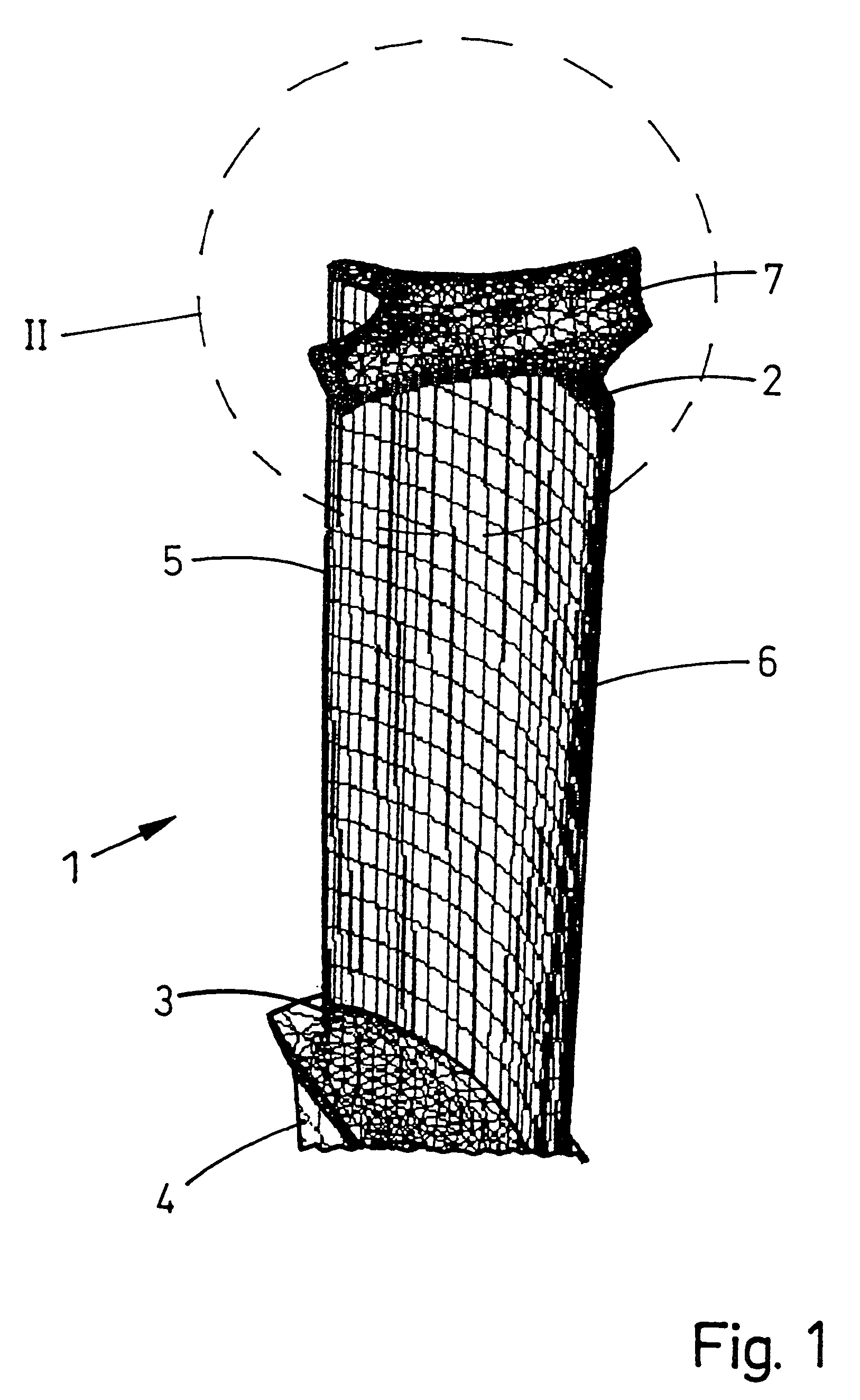
[0022]FIG. 1 shows a perspective view of a lattice model of a turbine moving blade 1 having a shroud band segment 7. The turbine moving blade 1 has a blade tip 2 at its top end and a blade root 3 at its bottom end, the blade root 3 continuing in a shank 4 (shown only approximately). The airfoil leading edge 5 is shown on the left-hand side of the drawing and the airfoil trailing edge 6 is shown on the right-hand side of the drawing.

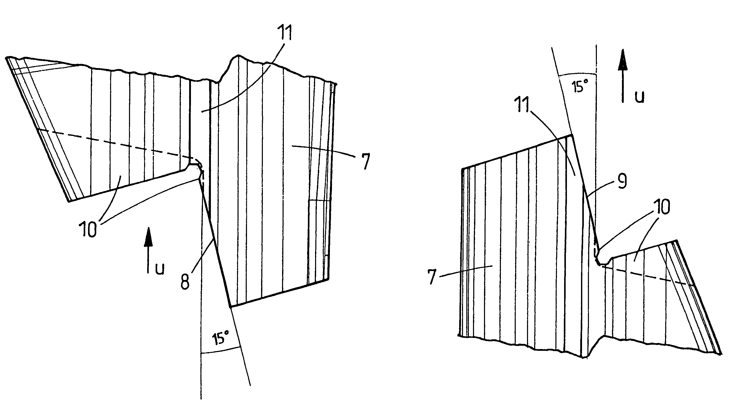
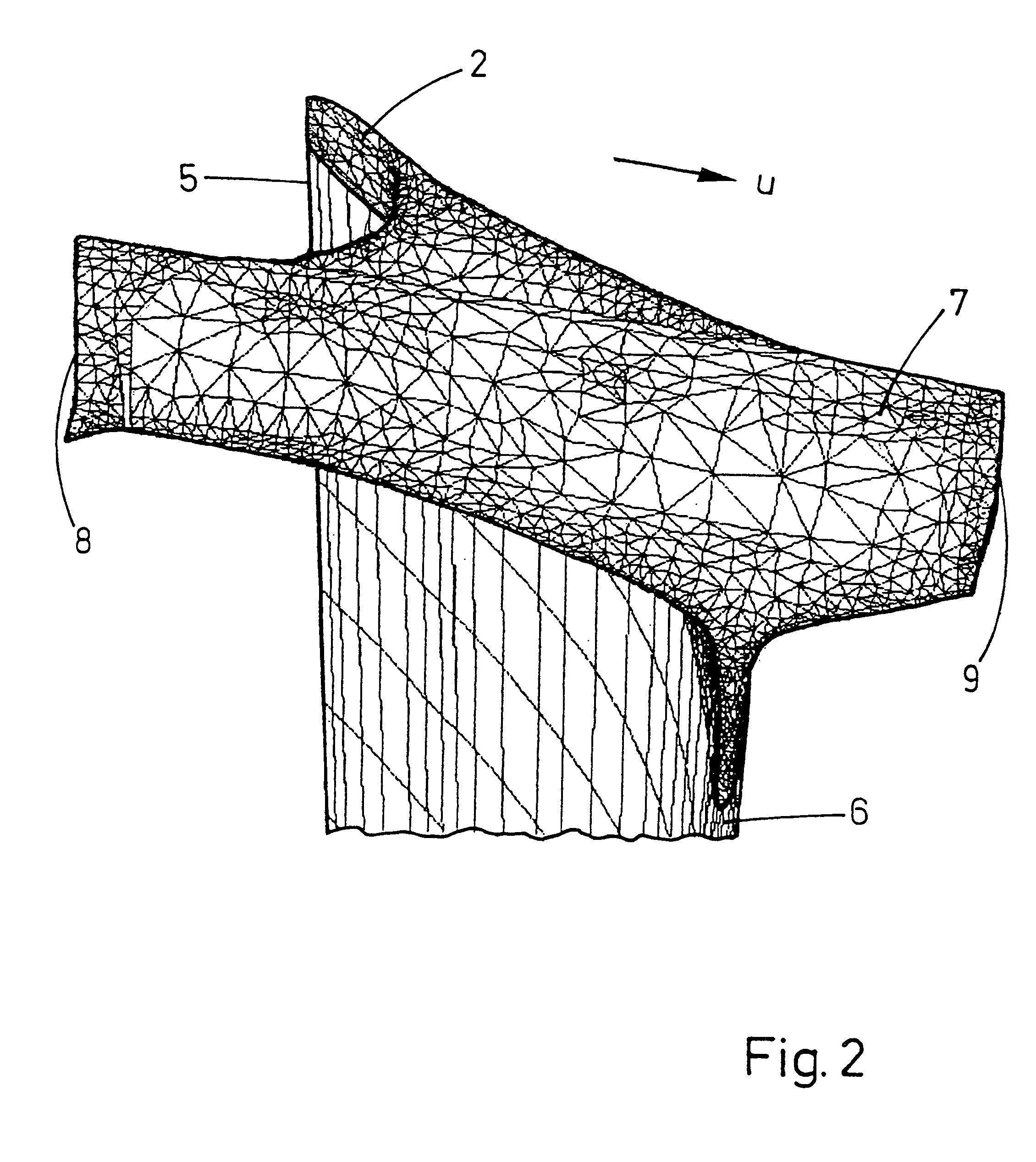
[0023]As can be seen in particular in FIG. 2 of the illustration of the detail II from FIG. 1, the shroud band segment 7 on the blade tip 2 runs essentially transversely to the airfoil chord running between the airfoil leading edge 5 and the airfoil trailing edge 6 and parallel to the circumferential direction U. In this case, the shroud band segment 7 does not extend over the entire blade depth but only to a region in the blade center. The transition between the shroud band segment 7 and the blade tip 2 is determined by transition radii. Furthermore, con...


PUM

PropertyMeasurementUnit
coupling angleaaaaaaaaaa

Abstract

A method of modifying a coupling geometry in a shroud band segment of a turbine moving blade includes the following steps: calculation of a modified coupling geometry; removal of shroud band material situated outside the modified coupling geometry; and / or application of additional material not present inside the modified coupling geometry; reworking the removal and / or application zones. The method avoids disadvantages of the prior art and provides improved wear behavior in the coupling region so as to prolong the life of the turbine blades in an effective and inexpensive manner.

Description

[0001]Priority is claimed to German Patent Application No. 103 28 310.2, filed on Jun. 23, 2003, the entire disclosure of which is incorporated by reference herein.[0002]The present invention relates to a method of modifying a coupling geometry in a shroud band segment of a turbine moving blade.BACKGROUND[0003]In turbine stages, it is known to provide turbine moving blades with a shroud band. In this case, the shroud band coupling of the blades or blade segments lying next to one another is characterized by a defined coupling angle, which, however, is affected by centrifugal forces acting on the blades, by the blade untwisting, by the shroud band stretching, by the temperature of the working medium, etc. The stresses which act during the mutual support of the blades during operation can in turn be controlled by the coupling angle and the coupling area. Such turbine moving blades having a shroud band segment are described, for example, in German patent DE 36 20 162 C2, related to U.S...

Claims


Application Information

Patent Timeline
Patent Type & Authority Patents(United States)
IPC IPC(8): B23P6/00F01D5/00F01D5/22
CPCF01D5/005F01D5/225Y10T29/49336Y10T29/49716Y10T29/49318Y10T29/49316
Inventor HAEHNLE, HARTMUTNAGLER, CHRISTOPHSCHWARZ, INGO
Owner ALSTOM TECH LTD
Why Eureka
Try Eureka