Endoscopic fluid supply conduit system

a fluid supply and conduit technology, applied in the field of endoscopic fluid supply conduit systems, can solve the problems of insufficient pump pressure and inconvenient use of the fluid injection channel of the above-mentioned prior ar

Inactive Publication Date: 2010-01-12
FUJI PHOTO OPTICAL CO LTD
View PDF8 Cites 29 Cited by
  • Summary
  • Abstract
  • Description
  • Claims
  • Application Information

AI Technical Summary

Benefits of technology

[0012]It is still another object of the present invention to provide an endoscopic fluid supply conduit system which permits to supply a fluid selectively either from a manipulating head assembly or from a universal cable of an endoscope without increasing the diameter of the insertion tube.
[0014]According to the present invention, two fluid supply channels are provided internally of an endoscope to supply a fluid to a fluid jet injection port which is opened on a rigid tip end section at the fore distal end of the insertion tube of the endoscope. With the fluid supply conduit system according to the present invention, it is possible to select fluid supply either from a fluid feed port which is provided on a manipulating head assembly of the endoscope or from and through a universal cable of the endoscope. That is to say, the fluid supply conduit system is provided with first and second fluid conduits which can be selected by the fluid supply channel selector means. When a fluid is fed into the first fluid conduit through the fluid connection port, the supplied fluid is prevented from flowing into the second fluid conduit. On the other hand, when a fluid is supplied to the endoscope from the side of the second fluid conduit, the supplied fluid is prevented from flowing out of the fluid feed port on the manipulating head assembly of the endoscope.
[0015]In a preferred form of the present invention, the fluid supply channel selector means is constituted by a mouth piece which is fixedly fitted in the fluid feed port on the manipulating head assembly of the endoscope, the mouth piece having a first connection port provided at an inner axial end for connection of the first fluid conduit and a second connection port provided at one side for connection of the second fluid conduit. When a fluid feed adaptor is fitted into the mouth piece, the second connection port is closed by the fluid feed adaptor. When the fluid feed adaptor is removed from the mouth piece and instead a plug member is fitted to close an outer open end of the mouth piece, the first and second fluid conduits are communicated with each other, permitting fluid supply from the second to the first fluid conduit while preventing fluid leaks through the mouth piece.
[0016]In another preferred form of the present invention, the second fluid conduit is joined with a halfway point of the first fluid conduit within a casing of the manipulating head assembly, and a reverse flow checking valve is inserted in the second fluid conduit at the junction point with the first fluid conduit to prevent a fluid flowing in a reverse direction toward the second fluid conduit from the side of the first fluid conduit.

Problems solved by technology

However, in some cases the pump pressure is found insufficient to supply a fluid under a predetermined pressure.
However, in the case of the above-mentioned prior art, a syringe or a pressure feed means which is set on the manipulating head assembly of the endoscope is used as an auxiliary means for boosting the pressure of a fluid which is supplied through a fluid supply channel on the side of the universal cable, and not used as means for supplying a fluid from the side of manipulating head assembly independently of a pump.
Namely, the fluid injection channel of the above-mentioned prior art is not suitable for use in such cases where a necessary amount of a fluid has to be supplied under a certain pressure according to judgements of an operator.

Method used


Image

  • Endoscopic fluid supply conduit system
  • Endoscopic fluid supply conduit system
  • Endoscopic fluid supply conduit system

Examples


second embodiment

[0035]Turning now to FIGS. 4 and 5, there is shown the present invention. In this embodiment, the first and second fluid conduits 4 and 5 are joined together through a junction pipe member which is provided within the casing of the manipulating head assembly, preventing fluid flow into the second fluid conduit 5 from the side of the first fluid conduit 4.

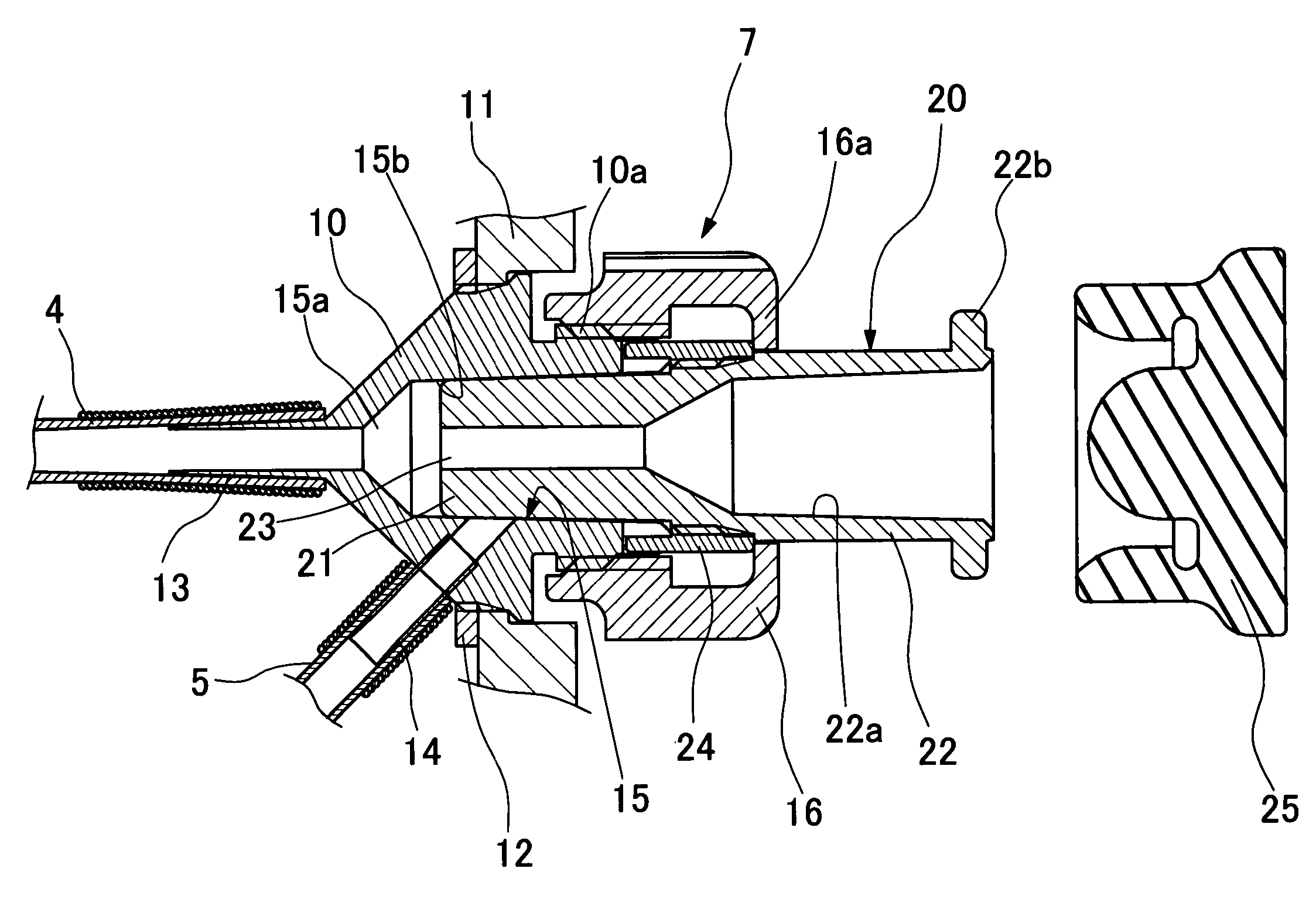
[0036]In FIG. 4, indicated by reference number 40 is a first fluid conduit leading to a fluid jet injection port at the fore distal end of the insertion tube of the endoscope, and by reference number 41 is a second fluid conduit which is connected to a fluid feed device through the universal cable of the endoscope. These first and second fluid conduits 40 and 41 are connected to first and second connecting portions 42a and 42b of a junction pipe member 42, respectively. The junction pipe member 42 is further provided with a third connecting portion 42c which is constantly in communication with the first fluid conduit 40. Connected t...

first embodiment

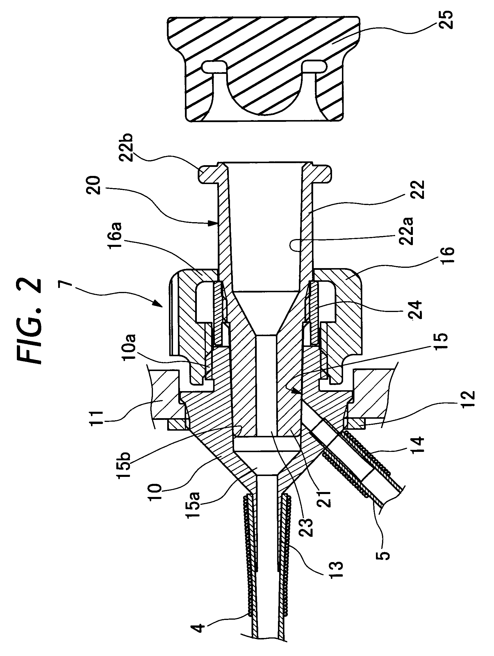
[0037]As seen in FIG. 5, the mouth piece 50 is arranged in a manner similar to the mouth piece 10 of the first embodiment shown in FIGS. 2 and 3. The mouth piece 50 is provided with a connection port 51 which corresponds to the first connection port of the mouth piece 10, but in this case the mouth piece 50 is not provided with a second connection port at its side portion. Since the mouth piece 50 is provided with a Luer taper portion 53 in its receptacle bore 52, a syringe or a similar fluid feed means can be connected to the mouth piece 50 directly or by way of a fluid feed adaptor 20 as shown in FIG. 2.

[0038]The second fluid conduit 41 is connected to the second connecting portion 42b of the junction pipe 42 not directly but through a reverse flow blocking or checking member 46. This reverse flow checking member 46 is in a tubular pipe-like form having one end thereof connected to the second fluid conduit 41 and the other end in threaded engagement with the second connecting port...


PUM


Abstract

An endoscopic fluid supply conduit system for use with an endoscope having an insertion tube and a universal cable connected to and from a manipulating head assembly. A fluid conduit is provided internally of the insertion tube to supply a fluid from a fluid feed port on the manipulating head assembly toward a fluid jet injection port feed port which is provided on a rigid tip end section at the fore distal end of the insertion tube. In addition, a second fluid conduit is provided internally of the universal cable and toward the manipulating head assembly. A fluid supply channel selector is provided at the fluid feed port to which a fluid feed adaptor is to be disconnectibly connected. The fluid supply channel selector is adapted to block a fluid flow toward the second fluid conduit when a fluid is supplied to the first fluid conduit from the fluid feed port on the manipulating head assembly, and to bring the second fluid conduit into communication with the first fluid conduit when the fluid feed port on the manipulating head assembly is closed.

Description

BACKGROUND OF THE INVENTION[0001]1. Field of the Art[0002]This invention relates to a fluid supply conduit system suitable for use on medical endoscopes in charging and discharging a fluid to and from a body cavity, and more particularly to an endoscopic conduit system capable of supplying a fluid selectively either from a fluid supply source connected to a fluid feed port on a manipulating head assembly of an endoscope or from a fluid supply source connected to a universal cable of the endoscope.[0003]2. Prior Art[0004]Generally, medical endoscopes are largely constituted by a manipulating head assembly to be gripped and manipulated by an operator for controlling various endoscopic operations, an elongated insertion tube connected to a front side of the manipulating head assembly for insertion into a body cavity of a patient, and a universal cable led out on the rear side of the manipulating head assembly. The universal cable is disconnectibly connectible at least to a light source...

Claims


Application Information

Patent Timeline
Patent Type & Authority Patents(United States)
IPC IPC(8): A61B1/00A61B1/012A61B1/12
CPCA61B1/00068A61B1/012A61B1/12
Inventor AKIBA, HARUO
Owner FUJI PHOTO OPTICAL CO LTD
Why Eureka
Try Eureka